What Is Phase Matching in Coaxial Cables & How to Make Phase Matched RF Cables

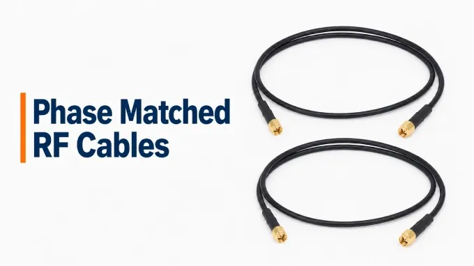
Phase matched RF cables are cable assemblies whose phase shifts match one another or a defined reference within a specified tolerance. That match applies at stated frequencies and under defined test conditions. These cables help preserve the intended phase relationship between signals travelling through separate paths. This matters when an RF system combines signals from several paths or uses phase differences to make a measurement.
How Does RF Cable Phase Matching Work?
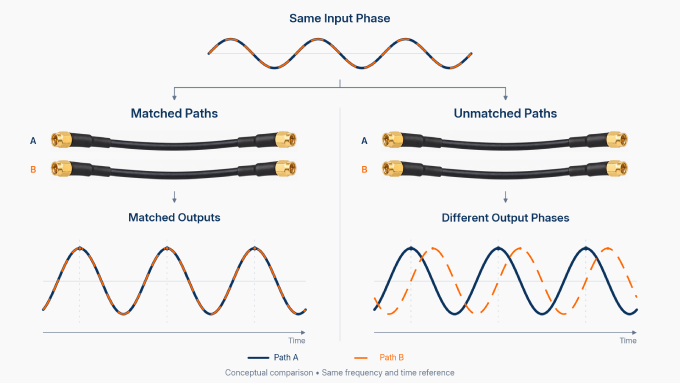
RF cable phase matching works by controlling each assembly’s electrical length, which expresses the phase shift through the assembly at a specified frequency.
Phase describes a signal’s position within a repeating cycle. When a signal travels through a cable, the propagation delay produces a phase shift between the input and output signals. If identical, synchronized signals enter two cables with different delays, they can emerge at different points in their cycles.
Which Factors Affect RF Cable Phase Matching?
A phase match depends on the assemblies’ construction and the conditions under which they are compared. The main factors are:
Physical Length: Differences in cable length introduce differences in signal travel time, even when the assemblies use the same cable type.
Propagation Speed: The RF cable velocity factor expresses propagation speed relative to the speed of light in free space. Variations in dielectric properties and cable construction can give cables of equal physical length different electrical lengths.
Operating Frequency: The same delay difference produces a larger phase difference at higher frequencies. Meeting a fixed tolerance in degrees therefore requires closer control of electrical length as frequency increases.
Connectors and Terminations: Connectors contribute to the assembly’s electrical length. Differences in connector design or how the connectors are fitted can affect the finished phase match.
Temperature and Mechanical Stress: Heating, cooling, bending, twisting, or pulling can change electrical length after matching. These effects determine how well an established match survives installation and use, as explained in the phase-stability section.
Why Are Phase Matched Cables Important, and Where Are They Used?
Phase matched cables are important in RF systems that depend on a known phase or timing relationship between signal paths. They limit unwanted phase differences introduced by the connecting cables, helping the system maintain the relationships its design requires.
Application | What Cable Matching Helps Preserve |
Phased-array radar and beamforming | The intended phase relationships used to shape and steer the beam |
Coherent receivers and direction-finding systems | The accuracy of phase comparisons between receiver channels |
Multichannel RF testing and antenna measurements | The accuracy of measurements made through separate cable paths |
Communications systems using coherent antenna channels | The intended relationship between signals carried by different antenna channels |
Consider a phased array whose antenna elements receive signals through separate cables. The system deliberately adjusts the signals’ phases to steer the beam. If the cables introduce unintended differences, those errors can alter the beam’s direction or shape. Engineers use phased-array cable-delay matching to control this source of error, giving the system a consistent starting point for its steering adjustments.
Cable matching can also simplify calibration by reducing the differences the system must compensate for. Matched cables do not create synchronization by themselves, however. The signal sources, timing references, and control electronics must establish the required relationship between channels.
What Are the Different Types of RF Cable Phase Matching?
RF cables can be phase matched to one another within a set or to a defined reference. These approaches are called relative and absolute phase matching.
Relative Phase Matching: The assemblies in a designated pair or set must match one another within the specified tolerance.
Absolute Phase Matching: Each assembly must meet a defined electrical-length or delay target within the specified tolerance. A numerical specification or retained reference assembly establishes the target.
Two separately supplied pairs can each meet the same relative matching tolerance while differing from one another. For example, both cables in one pair might introduce slightly more delay than both cables in the other pair. Combining cables from those pairs does not automatically produce a matched set.
A separate question is whether the match must hold at one frequency or across a frequency range. Assemblies that agree at a single test frequency may behave differently elsewhere in the band. Either matching approach must therefore identify the frequencies at which the requirement applies. Broadband applications may also specify delay matching to control differences in signal travel time across the operating range, particularly when the signals contain components at many frequencies.
What Is the Difference Between Phase Matching and Phase Stability?
Phase matching describes agreement between cable assemblies under specified conditions. Phase stability describes how much an assembly’s phase changes when those conditions change. A third term, phase tracking, describes how closely the assemblies change together.
Phase Matching: How closely do the assemblies agree at the specified frequencies and conditions?
Phase Stability: How much does an assembly’s phase change with temperature, movement, or bending?
Phase Tracking: How closely do the phase changes of different assemblies follow one another?
Two cables can have good phase stability yet begin with different electrical lengths. Likewise, cables that match on the test bench can drift apart after installation.
Suppose one cable in a matched pair runs beside a warm amplifier while the other stays cooler. Unequal heating can change their electrical lengths by different amounts, increasing the phase difference between them. If both cables instead change by similar amounts, they can retain their relative match even as their individual phases shift.
Installation and handling therefore matter:
Plan cable routes so the assemblies fit without being stretched or forced into position.
Keep bends within the manufacturer’s stated limits and avoid kinks or unnecessary movement.
Support the assemblies so pulling or twisting forces do not reach the connector terminations.
Account for differences in temperature exposure, including nearby heat sources and uneven airflow.
How Phase Matched Cable Assemblies Are Manufactured
Both the cable and its connector terminations need controlled manufacturing. Flexible, semi-rigid, and hand-formable assemblies can all be phase matched, although the production sequence varies with their construction and requirements.
Choose Suitable Components. The manufacturer selects cable and connectors for the operating frequency and checks that their electrical characteristics are consistent enough to achieve the required matching tolerance.
Condition the Cable Where Required. Some constructions or specifications call for controlled temperature cycles or other stabilization before final matching. This helps reduce later changes that could disturb the completed match.
Cut and Prepare the Cable. The cable is cut and stripped to controlled dimensions, then prepared for its connector terminations. If trimming is planned, the initial cut leaves enough material for adjustment.
Measure and Adjust the Electrical Length. Measurements guide the adjustment. Trimming removes small amounts of cable to reach the target. As an alternative to individual adjustment, manufacturers can measure finished assemblies and select those that already match.
Complete the Assembly. The manufacturer finishes the connectors, adds the specified protection, and forms the cable as required. Any operations that could affect the assembly’s electrical response must be completed before final verification.
How the Finished Phase Matched Cables Are Tested
The completed assemblies are electrically measured and compared at the specified frequencies. Testing covers the full signal path through each assembly, including both connector terminations.
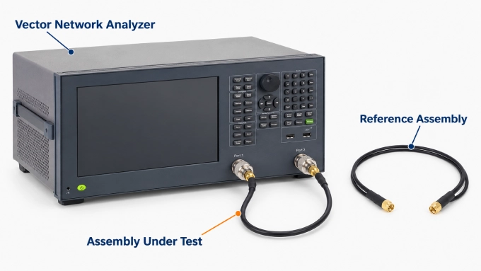
Manufacturers commonly use a vector network analyzer (VNA), an instrument that measures how RF components affect a signal. A calibrated VNA measures each assembly’s phase response for comparison with the defined reference or the other cables in the set. The assemblies are tested under the conditions stated in the specification.
For broadband applications, RF group delay measurement can also help check how closely the assemblies’ delays agree across the operating band.
The test report must show:
Identification of each assembly and its matched set.
The reference or target used for comparison.
The test frequencies or frequency range.
The temperature and other relevant test conditions.
The measured phase or delay differences and the applicable limits.
What Should You Check When Choosing Phase Matched Cable Assemblies?
Check the tolerance together with its reference, frequency coverage, and test conditions. These details establish what the supplier guarantees and whether that guarantee covers your application.
Operating Frequency: Confirm the frequencies or frequency range over which the cables must match.
Phase or Delay Tolerance: Specify the permitted difference, with the appropriate units and frequency conditions.
Matching Basis: Confirm whether the requirement applies within a designated set or against a defined reference.
Set Size: State how many assemblies must match and how each set will be identified.
Physical Configuration: Specify connector interfaces, assembly lengths, and routing requirements, including any required bends.
Operating Conditions: Describe the expected temperature range and whether the cables will remain fixed or move during use.
Test Data: Check that measurement results demonstrate compliance with the agreed requirement.
Ask whether the tolerance applies to each cable against a reference or to the largest permitted difference between cables in the set. Those limits are not interchangeable.
Tighter tolerances can increase manufacturing effort and cost, so choose a limit that reflects the system’s needs. When requesting custom RF cable assemblies, provide these requirements together so the supplier can assess the complete configuration.
FAQ
Discussion (0)
Be the first to comment.