What Is an RF Power Splitter? Types, Theory & Applications

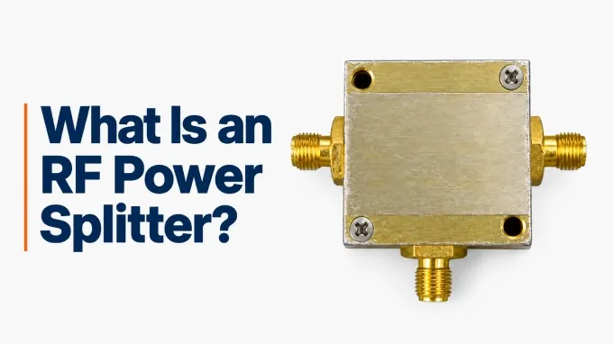
An RF (radio frequency) power splitter, also called an RF power divider, is typically a passive device that divides one incoming RF signal into two or more output signals. It is designed to operate at a specified system impedance, commonly 50 Ω or 75 Ω.
When used as a splitter, the input is called the common port, and the outputs are branch ports. An N-way splitter has N outputs and normally N + 1 ports in total. For example, a two-way splitter has one input and two outputs.
Each output carries the same RF signal content. Equal-split designs distribute power evenly between the outputs; unequal-split designs distribute it according to a specified ratio. This allows one source to supply multiple signal paths—for example, one antenna feeding two receivers.
How Does an RF Power Splitter Work?
An RF splitter uses resistors, transmission lines, or transformers to divide input power between its outputs. Its circuit also controls impedance matching and coupling between the output branches.
How Much Power Reaches Each Output?
An equal-split device gives each output the same share of the input power. For N outputs, assuming matched ports and no excess loss:
Here, is the number of outputs, is the input power, and is the power delivered to each output.
Splitter | Power per output | Ideal splitting loss per path |
2-way | 50% of input | 3.01 dB |
4-way | 25% of input | 6.02 dB |
8-way | 12.5% of input | 9.03 dB |
Splitting loss is the reduction at each output because the power is shared. Excess loss is additional attenuation caused by the real circuit.
A matched three-resistor divider, for example, has approximately 6 dB of attenuation per path: 3 dB from power division and another 3 dB from resistor dissipation. With a 10 dBm input, a matched two-way splitter with 0.5 dB excess loss per path delivers approximately 6.5 dBm at each output.
How Splitters Limit Reflections and Coupling Between Outputs
Impedance matching keeps a port’s impedance close to the system value under specified load conditions, reducing reflected power. Simply connecting two 50 Ω loads in parallel with a tee presents 25 Ω at the junction. This creates a mismatch in a 50 Ω system and reflects some power toward the source.
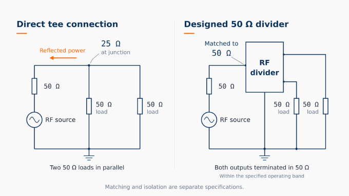
Port isolation measures how much a signal entering one output branch is attenuated before reaching another. Higher isolation means that reflections or signals from one connected device have less effect on the other branches. Good impedance matching alone does not guarantee high isolation.
Isolation is finite, so some branch coupling remains. Common-port matching also matters: a mismatch there can reflect signals back through the branches and reduce effective isolation. Splitter performance therefore depends on both its circuit and the impedances connected to its ports.
Applications of RF Splitters
RF splitters are used in antenna feeds, receiver systems, test setups, and amplifier networks. Each application has different requirements for delivered signal power, isolation between paths, and phase relationships.
Antenna and array feeds. A splitter distributes one RF source among antenna elements, often through phase shifters or gain controls. The feed network must preserve the intended amplitude and phase relationships so the array produces the required radiation pattern.
Local oscillator distribution. A splitter connects one local oscillator (LO) to several mixers, giving multiple frequency-conversion paths a common frequency source. Each mixer must receive its specified LO drive level after splitter and interconnection losses, including on the branch with the greatest loss.
Shared-antenna reception. A splitter allows multiple receivers to use one antenna—for example, several GNSS receivers sharing a vehicle-mounted antenna. Low path loss preserves adequate signal strength, while output isolation helps prevent signals or reflections from one receiver from disturbing another.
Laboratory and production testing. A splitter sends one generator’s signal to several test paths, or feeds both a device under test and a reference detector or receiver. Accurate measurements require predictable signal levels, appropriate source matching, and a circuit suited to the measurement arrangement.
What Is the Difference Between a Power Divider and an RF Splitter?
Term | Signal direction | Common use | Key qualification |
RF splitter | One input to multiple outputs | Signal distribution for source leveling and ratio measurements | The names are usually interchangeable Two-resistor design, effective matched source at the test branch in leveling or ratio measurements |
RF Divider | One input to multiple outputs | Signal distribution and independent measurements | Matched two-way three-resistor design, approximately 6 dB attenuation per output |
RF combiner | Multiple inputs to one output | Combine RF signals or amplifier outputs | Combining efficiency depends on the input signals |
RF Power Divider vs Splitter Design
RF power splitter and RF power divider usually refer to the same device. Some test-equipment manufacturers use the names to distinguish two specific resistive circuits:
Power divider: Three equal resistors, used for general signal distribution and independent measurements.
Power splitter: Two resistors in the output branches, used for source leveling and ratio measurements.
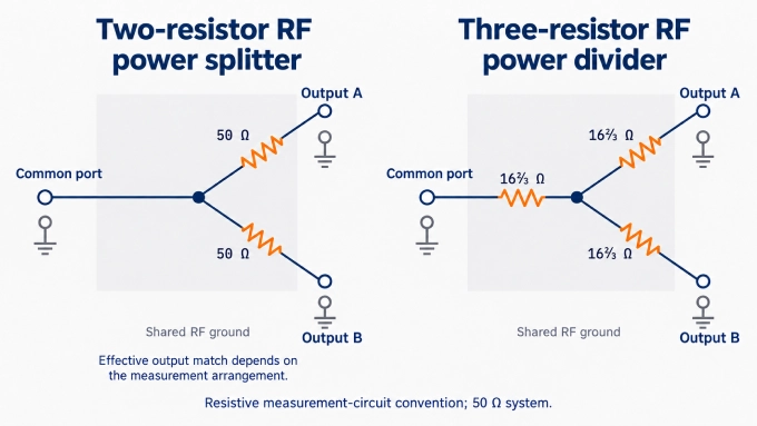
In the two-resistor arrangement, one output feeds the device under test and the other feeds a reference detector or receiver. Source leveling uses the reference to adjust the generator and keep its signal level steady. Ratio measurement compares the device’s response with the reference, reducing errors caused by changes in source output.
In this measurement arrangement, the two-resistor circuit can provide an effective 50 Ω source impedance at the test branch. That benefit depends on the reference configuration; it does not establish ordinary 50 Ω matching at every port.
RF Splitter vs RF Combiner
Many passive RF splitters can work as combiners when the signal direction is reversed: feed signals into the branch ports and take the combined output from the common port. Check that the device’s specifications support the intended combining conditions.
The output depends on how the input waves add together. At the same frequency, signals can reinforce or cancel according to their relative phase. Their amplitudes also affect how efficiently their power combines.
Coherent signals maintain a fixed phase relationship. In-phase signals have zero relative phase. Coherent inputs can therefore still have the wrong phase relationship for efficient combining.
For same-frequency inputs, an ideal matched two-way 0° isolated combiner follows:
Here, and are the input powers, and is their relative phase at the input ports.
With 1 W at each input, the ideal results are:
Input relationship | Combined output | Power dissipated in isolation load |
Same frequency, in phase | 2 W | 0 W |
Same frequency, 180° apart | 0 W | 2 W |
Different frequencies, both within the operating band | 1 W total: 0.5 W at each frequency | 1 W |
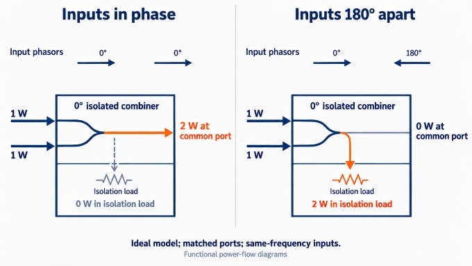
In this ideal model, power that does not reach the output becomes heat in the isolation load. Unequal input amplitudes also cause dissipation, even when the signals are in phase. Practical devices add circuit losses.
The required input phase relationship depends on the combiner design; a 90° hybrid requires different phasing from a 0° combiner. Active splitters should not be assumed to work in reverse.
What Are the Different Types of RF Power Splitters?
Four common RF splitter designs are resistive, Wilkinson, transformer-based, and hybrid. The choice depends on the required bandwidth, excess loss, isolation, and output phase.
Circuit type, port count, division ratio, and packaging describe different properties. Microstrip and stripline are transmission-line structures; LTCC and MMIC are fabrication technologies; connectorized describes the external interface. A Wilkinson divider, for example, can use microstrip lines inside a connectorized enclosure.
Active splitters add amplification to offset splitting loss or provide gain. They require a power supply and introduce noise and linearity limits. Their amplifiers have a preferred signal direction, so reverse operation as a combiner requires explicit support from the manufacturer.
Resistive RF Splitters
Resistive RF splitters divide the signal through a network of resistors. Their simple construction supports broad frequency coverage, potentially including DC, because they do not depend on quarter-wave transmission lines or magnetic coupling. At higher frequencies, resistor, package, and board parasitics limit performance.
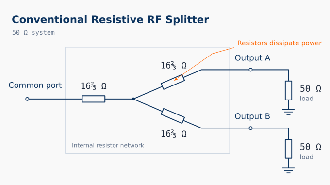
The tradeoff is resistor dissipation and limited output isolation, as discussed earlier. Choose this approach when wide frequency coverage matters more than preserving signal power or separating the branches. Designs that add reactive or isolation circuitry can perform differently from conventional resistive networks.
Wilkinson Power Dividers
A classic equal two-way Wilkinson divider uses two quarter-wave transmission lines and a resistor connected between its outputs. Each line is one-quarter of the guided wavelength at the design frequency—an electrical length of 90°.
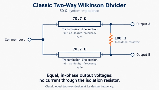
For system impedance , the classic design uses:
Here, is each branch line’s characteristic impedance, and R is the isolation resistance.
During ideal balanced splitting into matched loads, both outputs have equal voltages and phases. No voltage appears across the resistor, so it dissipates no power. Differences between the branch signals drive current through the resistor, which absorbs that difference energy and provides isolation.
This makes Wilkinson dividers useful for low excess loss and isolated, in-phase outputs. The classic single-section design has limited bandwidth; multisection designs can broaden it, while lumped-element versions replace the lines with inductor-capacitor networks.
Transformer-Based RF Splitters
Transformer-based splitters use coupled windings or transmission-line transformers to divide the signal and transform impedances. They can provide low excess loss over a broad specified band, making them useful for suitable lower-frequency RF applications.
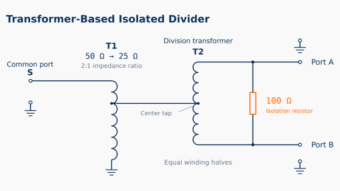
Output isolation requires an appropriate circuit arrangement, often combining transformer action with a resistor; a transformer alone does not guarantee isolated branches. Core behavior, winding parasitics, and construction determine the usable bandwidth and power handling. These limits vary by design, so there is no universal frequency range for this family.
Hybrid Splitters for Defined Phase Relationships
Hybrid splitters are four-port networks used when a system needs controlled output phase relationships, such as quadrature or balanced signal paths. The relative phase between the two outputs depends on the hybrid type and which port is driven.
Hybrid and driven port | Nominal phase relationship between outputs |
90° hybrid, designated input | 90° apart |
180° hybrid, sum port | In phase |
180° hybrid, difference port | 180° apart |
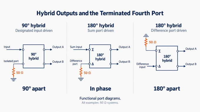
A 180° hybrid can also form the sum and difference of two input signals.
When used as a two-way splitter, the fourth port is ideally isolated from the driven port. A matched termination there preserves the intended matching and isolation and absorbs energy diverted by imbalance or reflections.
Key Specifications for Selecting RF Power Splitters and Dividers
First identify whether the device will split or combine signals, the required branch count, the intended power ratio, and the phase relationship. Then check these specifications against the system’s requirements.
Electrical Specifications
Frequency range: The frequency band over which the device’s RF performance is specified. Choose a range covering every operating frequency, and check performance at the band edges using guaranteed limits where available.
Port impedance: The reference impedance for which the ports are designed, commonly 50 Ω or 75 Ω. Match it to the connected source, loads, and transmission lines.
Insertion loss: Signal attenuation through the device, expressed in dB. Check whether the datasheet reports total path attenuation or only excess loss. Use total attenuation to verify adequate receiver signal levels or mixer drive.
Amplitude balance and flatness: Balance describes how closely branch powers follow the intended split ratio; flatness describes each path’s attenuation variation with frequency. Choose imbalance and ripple limits that keep signal levels within the system’s tolerances.
Phase balance: How closely the phase difference between branches matches the intended relationship. Check the permitted phase error across the operating band relative to the required relationship, such as 0°, 90°, or 180°.
Port isolation: The attenuation a signal experiences when travelling from one branch port to another. Check every relevant branch pair and choose isolation sufficient to keep coupling acceptable with the connected loads.
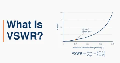
Return loss or VSWR: Measures of reflections caused by impedance mismatch. Higher return loss and lower VSWR indicate better matching. Check the common and branch ports under the stated termination conditions, using limits appropriate to the required power delivery and measurement accuracy.
Power Ratings and Terminations
Check average and peak RF power limits where specified, including power per input and any separate splitter and combiner ratings. Internal resistor or isolation-load dissipation can limit combining power. Account for unequal inputs, loss of one drive signal, and reflected power when assessing that limit.
Terminate unused RF ports with matched loads rated for the expected power. Confirm the temperature and mounting conditions attached to the device and termination ratings.
Cables and Connections
Confirm connector compatibility, mechanical fit, and any required DC routing. For tight branch balance, specify custom RF cable assemblies with controlled attenuation and electrical length. Equal physical lengths do not guarantee phase matching. Evaluate signal power and phase at the connected devices, because splitter-port specifications do not include the effects of the interconnecting cables.
FAQ
Discussion (0)
Be the first to comment.