50 Ohm vs 75 Ohm Coaxial Cable: Which Should You Use?

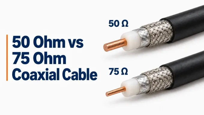
50 Ω and 75 Ω are the two most common characteristic impedance standards for coaxial cable. Their uses reflect different engineering priorities: a 50ohm coaxial cable offers a practical balance between power handling and attenuation for RF systems, while 75 Ω coax is widely used in television and video distribution and is close to the minimum-loss impedance of air-filled coax. Below is a general comparison between 50 ohm and 75 ohm coaxial cables:
Comparison criterion | 50 Ω coax | 75 Ω coax |
Center-conductor diameter | Larger | Smaller |
Conductor loss in ideal air-filled coax | Higher | Lower |
Conductor loss in ideal solid-polyethylene coax | Lower | Higher |
Theoretical peak power capacity | Higher | Lower |
Capacitance, at the same propagation velocity | Higher | Approximately two-thirds of the 50 Ω value |
Typical applications | RF transmission and measurement | Television, video, and signal distribution |
Common cable families | RG-58, RG-213 | RG-6, RG-59 |
Note: Loss comparisons assume the same shield inner diameter, copper conductors, and operating frequency. Peak-power comparison assumes the same shield inner diameter, dielectric, and allowable electric field. These are controlled comparisons rather than rankings of every commercially available cable.
Construction: What Makes a Cable 50 Ω or 75 Ω?
Conductor geometry and dielectric properties determine whether a cable is 50 Ω or 75 Ω. Both types contain a center conductor, an insulating dielectric, an outer conductor or shield, and a protective jacket. The controlling geometry is the ratio between the shield’s inner diameter and the center conductor’s diameter.
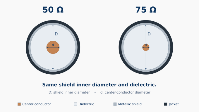
For low-loss coax with a uniform, nonmagnetic dielectric, the approximate relationship is:
Here, is characteristic impedance in ohms, is the shield’s inner diameter, is the center conductor’s diameter, and is the dielectric’s relative permittivity. Both diameters must use the same units.
With the same shield inner diameter and dielectric, 75 Ω requires a smaller center conductor than 50 Ω. Changing the dielectric changes the diameter ratio required for either impedance, so solid- and foam-dielectric cables can have different dimensions despite sharing the same rating. Jacket thickness and cable length do not set nominal characteristic impedance.
How Can You Tell Whether a Coaxial Cable Is 50 or 75 Ohms?
Check the printing on the cable jacket, exact manufacturer part number, or datasheet. Familiar cable designations such as RG-58 and RG-213 are normally 50 ohms, while RG-6 and RG-59 are commonly 75 ohms. Visual inspection alone is unreliable. An ordinary resistance measurement cannot establish characteristic impedance; see our characteristic-impedance measurement guide.
50 Ohm vs 75 Ohm: Attenuation and Signal Loss
For ideal coax with copper conductors and the same shield inner diameter, 75 Ω has lower conductor loss with an air dielectric; 50 Ω has lower conductor loss with solid polyethylene. The corresponding minimum-loss impedances are approximately 77 Ω and 51 Ω. This is why “75 Ω always has lower loss” is an oversimplification.
In the foam-polyethylene example below, the 75 Ω cable has slightly lower attenuation at both frequencies. Both cables have a 10.29 mm outside diameter, although their center-conductor dimensions and materials differ. These are typical losses over 100 m at 25 °C, with each cable matched to its own impedance.
Frequency | Example 50 Ω cable | Example 75 Ω cable |
150 MHz | 5.0 dB | 4.8 dB |
900 MHz | 12.8 dB | 12.1 dB |
Similarly, an RG-6 cable can outperform a thinner 50 Ω cable because of its diameter and dielectric construction, rather than its impedance alone.
50 Ohm vs 75 Ohm: Average and Peak Power Handling
50 Ω has higher theoretical peak power capacity than 75 Ω when shield inner diameter, dielectric, and allowable electric field are the same. In the ideal coax model, its geometry is closer to the maximum-power geometry, which corresponds to approximately 30 Ω for air-filled coax. This explains 50 Ω’s role as a compromise between power handling and attenuation.
Peak power is limited by dielectric breakdown. Average power is limited by heating, so its ranking also involves conductor losses and heat dissipation. The same example cables have these published ratings:
Power rating | Example 50 Ω cable | Example 75 Ω cable |
Peak power | 16 kW | 10 kW |
Average power at 900 MHz | 580 W | 520 W |
The average-power ratings assume matched operation, 40 °C ambient temperature, a 100 °C center conductor, sea level, dry air at atmospheric pressure, and no solar loading. Mismatch can reduce allowable power by increasing local voltage and heating.
50 Ohm vs 75 Ohm: Frequency Range and Bandwidth
Neither impedance has a general bandwidth advantage. Both 50 Ω and 75 Ω cables support multi-gigahertz applications, including analog and digital transmission. For example, specialized 75 Ω video cables have specified performance extending to 12 GHz.
Usable bandwidth is the frequency range over which the cable satisfies the system’s attenuation and impedance-uniformity requirements. Cable dimensions and materials determine that performance. A long cable can exceed the system’s permitted loss while remaining below its rated maximum frequency, so maximum operating frequency and usable bandwidth are different limits.
Common Applications of 50 Ohm and 75 Ohm Coaxial Cables
50 Ω coax commonly connects radio transmitters and receivers to antennas, carries signals in wireless and cellular systems, and links RF test instruments to devices under test. iprece.com 75 Ω coax commonly carries television antenna, CATV, and satellite signals, along with analog video, SDI digital video, and coaxial S/PDIF digital audio. Cell-booster systems use either 50 Ω or 75 Ω cabling according to the impedance designed into each equipment port.
Which Should You Use: 50 Ohm or 75 Ohm Coax?
Match the cable to the equipment’s specified impedance: 50 Ω for a 50 Ω path and 75 Ω for a 75 Ω path. The first seven rows below concern a 75 Ω replacement in a 50 Ω system.
Application | Likely Result | Recommendation |
Scanner or general radio reception | Usually works with little noticeable degradation | Often acceptable for noncritical use |
Weak-signal reception | May work, but added loss can matter | Compare the complete installed performance |
Low-power narrowband transmission | Some equipment may tolerate the mismatch | Verify the installed VSWR and transmitter limits |
High-power transmission | Reflections and voltage or current peaks become more consequential | Use properly matched 50 ohm cable |
Broadband, pulse, or phase-sensitive systems | Mismatch can affect frequency response, pulse shape, or phase | Avoid unless the complete path is tested |
Precision RF measurement | Adds unwanted measurement uncertainty | Use a controlled 50 ohm cable assembly |
Permanent commercial or OEM system | Produces less predictable and repeatable performance | Maintain 50 ohms throughout the signal path |
Television/CATV and broadcast-video systems | 75 Ω cable preserves the specified impedance | Use a suitable 75 Ω coax |
50 Ohm vs 75 Ohm for Antenna
Radio transmitters and receivers commonly use 50 Ω interfaces, while television receiving equipment commonly uses 75 Ω. The antenna’s actual feed-point impedance varies with frequency and may include reactance; a nominal rating describes the intended interface rather than an exact impedance at every frequency.
For an informal receive-only setup, using available RG-6 may be a reasonable compromise. For transmitting, choose cable consistent with the specified feed system and verify the installed VSWR against the transmitter’s limits.
50 Ohm vs 75 Ohm for Cell Boosters
For a cell booster, match each cable path to its corresponding port specification. Both 50 Ω and 75 Ω systems exist, and one unit can specify 75 Ω at its outdoor port and 50 Ω at its indoor port.
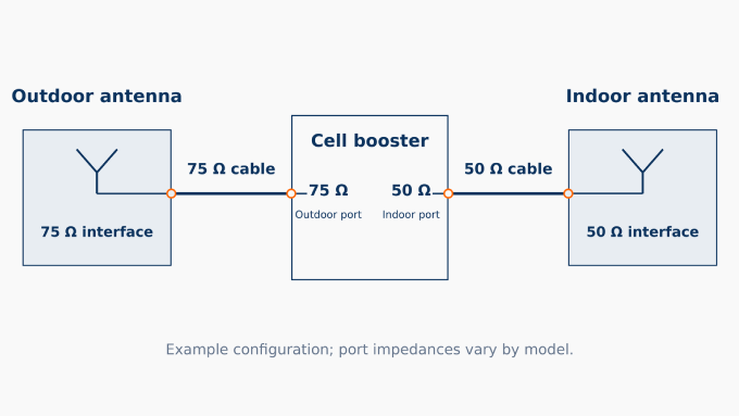
Check the outdoor and indoor port impedances separately in the installation manual.
Verify that each antenna, cable, splitter, and surge protector has the impedance required for the path where it is installed.
Follow the manufacturer’s component requirements, including approved cable types and permitted lengths.
Impedance alone does not determine booster gain, coverage area, data speed, or permissible cable length.
Does an RCA Connection Need 50 Ohm or 75 Ohm Coax?
Use 75 Ω coax for RCA connections carrying composite video, component video, or coaxial S/PDIF digital audio. Those interfaces specify 75 Ω transmission paths. The RCA plug shape alone does not establish a controlled 75 Ω impedance or identify the cable behind it.
Ordinary line-level analog audio generally does not require 50 Ω or 75 Ω transmission-line matching at typical interconnect lengths. Shielding, capacitance, and cable length are usually more relevant considerations. A suitable 75 Ω coax can carry analog audio without making the connected equipment a 75 Ω system.
What Happens If You Use 75 Ohm Coax Instead of 50 Ohm?
If you use a 75 ohm coax instead of 50 ohm, the signal will still be carried in a 50 ohm system, but it is not an electrically equivalent replacement.
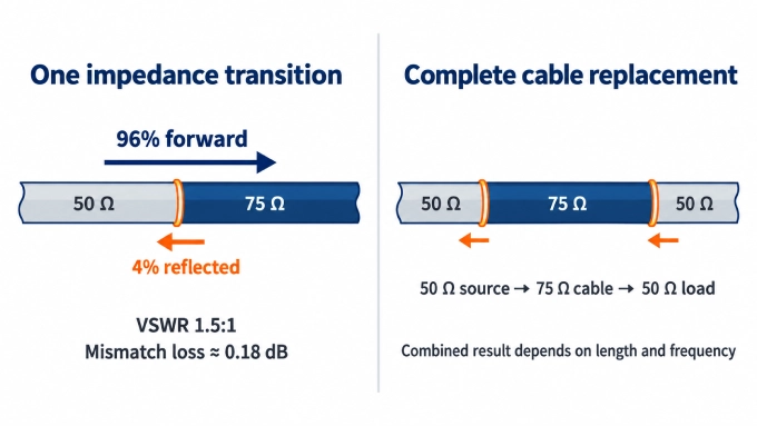
With nominally 50 ohm equipment ports, the substitution creates two impedance changes:
At the cable input: The signal moves from 50 ohm equipment into 75 ohm cable.
At the cable output: The signal moves from the 75 ohm cable back into a 50 ohm device or load.
At each transition, most of the signal continues forward while some is reflected. These reflections interact with the forward-traveling signal and produce standing waves inside the cable. The impedance seen by the equipment may therefore change with load impedance, frequency, cable electrical length, and attenuation rather than remaining at a fixed 50 ohms. This can affect VSWR, power transfer, and frequency response.
The reverse substitution, inserting 50 ohm cable into a 75 ohm path, also creates an impedance mismatch.
How Serious Is the 50 to 75 Ohm Impedance Mismatch?
The mismatch between 50 and 75 ohms is relatively modest. The figures below describe one ideal, lossless transition with real impedances and no further reflections from beyond that transition.
Here, is the incident line’s characteristic impedance, and is the impedance presented beyond the transition:
Measurement | Result | What It Means |
Reflection-coefficient magnitude | 0.20 | Reflected voltage magnitude is 20% of the incident voltage magnitude |
Reflected power | 4% | A small portion of the incident power is reflected at that transition |
Transmitted power | 96% | Most of the incident power crosses that individual transition |
Return loss | Approximately 14 dB | Describes the strength of the reflection |
VSWR | 1.5:1 | Indicates the standing-wave level at that transition |
Mismatch loss | Approximately 0.18 dB | Power unavailable beyond the transition because of the mismatch |
These quantities follow the standard relationships between reflection coefficient, reflected power, mismatch loss, VSWR and return loss.
Reflections from both ends interact, so the complete system does not necessarily have a fixed 1.5:1 VSWR or 0.18 dB mismatch loss. The individual transition losses cannot be added to predict a fixed complete-cable loss.
When Is Replacing 50 Ohm Coax With 75 Ohm Reasonable?
Replacing 50 ohm coax cable with 75 ohm cable is reasonable only when the practical benefit outweighs the uncertainty introduced by the mismatch. The substitution is easier to justify when:
The connection is receive-only or temporary.
Small performance changes are acceptable.
The available RG-6 has meaningfully lower attenuation than the available 50 ohm cable.
The system operates over a limited frequency range.
The complete installed path can be tested.
Stay with correctly matched 50 ohm coax when:
Transmitting significant RF power
Operating close to the available link margin
Measuring S-parameters or calibrating RF equipment
Carrying broadband, pulse, or phase-sensitive signals
Building a repeatable commercial or OEM system
Specifying a permanent custom RF cable assemblies
Can Using 75 Ohm Coax Damage the Transmitter?
Using 75 ohm coax does not automatically damage a 50 ohm transmitter. The risk depends on the transmitter’s output-stage design, its RF amplifier output impedance, and the impedance presented by the complete cable-and-load combination at the operating frequency—not on the cable label alone.
The practical risk differs by application:
Receive-only equipment: The mismatch may reduce the received signal, but it is unlikely to damage the receiver.
Low-power transmitters: Many tolerate moderate VSWR or automatically reduce their output power when the mismatch becomes excessive.
High-power or less-protected amplifiers: Reflected power can contribute to additional heating, reduced output, or excessive voltage and current stress.
A transmitter’s specified maximum load VSWR should determine whether the substitution is safe. If the manufacturer does not provide a clear limit, the installed system should be measured rather than assumed to present a constant 1.5:1 VSWR.
An antenna tuner can help, but its effect depends on where it is installed. A tuner at the transmitter output may transform the impedance so the transmitter sees a more acceptable load. It does not necessarily eliminate the standing waves or losses within the mismatched feedline itself.
FAQ
Discussion (0)
Be the first to comment.