CNT-400 vs LMR-400 Coaxial Cable: Key Differences in RF Performance

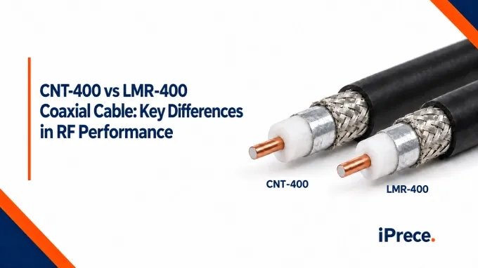
CNT-400 and LMR-400 are flexible, low-loss coaxial cables from the larger CNT and LMR cable families, with closely matched electrical, mechanical, and dimensional specifications. Neither is universally better; the right choice depends on operating frequency and cable length, continuous and peak power requirements, installation environment, compatible connectors and termination tools, and product availability. This comparison covers the standard CNT-400 and LMR-400 versions; direct-burial, fire-retardant, and high-flex variants may have different specifications.
CNT-400 vs LMR-400: Specifications at a Glance
Both products are 50 ohm coaxial cables with the same nominal outside diameter and broadly similar construction. These similarities make CNT-400 a potential alternative to LMR-400 in many fixed RF installations, but they do not make the cables automatically interchangeable. You must still check attenuation at the operating frequency, compatible connector designs, environmental qualifications, and finished-assembly performance.
CNT-400 vs LMR-400: Attenuation
Attenuation increases with frequency in both cables, but their published values remain closely matched across the shared comparison points. Here’s a comparison between the two coaxial cables at the same frequencies:
Neither cable has a consistent attenuation advantage across the listed frequencies. The largest difference shown is only 0.26 dB/100 m at 5.8 GHz. Because the LMR-400 values are identified as typical, these small discrepancies may reflect rounding or normal performance variation rather than a guaranteed advantage. For a strict loss budget, compare applicable specification limits or measured assembly data.
Translating Published Attenuation into Installed Loss
To estimate cable loss, multiply the published attenuation by the installed coaxial cable length:
For a 30 m run at 2.5 GHz:
CNT-400:
LMR-400:
Difference:
In this 30 m example, the calculated difference is only 0.06 dB. The complete coaxial cable signal loss budget must also account for connectors, adapters, surge protectors, temperature, manufacturing tolerances, and termination quality. When the available margin is small, evaluate the finished assembly rather than relying only on bulk-cable values.
CNT-400 vs LMR-400: Frequency Range and Power Handling
Frequency and power specifications are meaningful only when their definitions and test conditions match. Do not treat published maximum values as interchangeable with a qualified operating band or the capability of a finished cable assembly.
Published Frequency Figures vs Usable Assembly Bandwidth
The CNT-400 has an operating frequency band of 30 MHz to 6 GHz and a separate maximum-frequency value of 16.2 GHz. The LMR-400 datasheet provides attenuation values through 8 GHz but does not present that endpoint as directly equivalent to either CNT-400 figures.
These values describe different things:
An operating band identifies the range for which the manufacturer documents intended operation.
An attenuation table shows published loss values at selected frequencies.
A maximum-frequency field indicates an upper limit but does not, by itself, guarantee insertion loss, return loss, or assembly performance throughout that range.
Therefore, do not interpret the extent of a loss table as a qualified operating limit, and do not treat CNT-400’s 16.2 GHz maximum-frequency value as a guaranteed assembly bandwidth. Usable bandwidth also depends on cable length, connector interfaces, termination quality, return loss, and the permitted insertion-loss budget.
For operation beyond a clearly documented band, buyers should confirm the intended application and request assembly-level insertion-loss and return-loss limits across the full frequency range. Without those limits, the published information does not establish a clear CNT-400 vs LMR-400 frequency-range winner.
Peak Power vs Continuous Average Power
Both standard CNT and LMR cable list a peak-power rating of 16 kW, but peak power is not the same as continuous average power. Peak power is primarily constrained by the voltage the cable can withstand before dielectric breakdown, while average power is limited by heat generated through conductor and dielectric losses.
The CNT-400 datasheet provides the 16 kW peak rating but no frequency-dependent average-power table. Therefore, those documents do not support a complete numerical comparison with LMR-400, and you should not assign LMR-400 average-power values to CNT-400 based on similar construction alone.
For power-critical applications, obtain an average-power rating at the operating frequency and apply the necessary derating for VSWR, duty cycle, ambient temperature, solar exposure, routing, and heat dissipation. Finished custom RF cable assemblies are limited by their lowest-rated connectors or other components.
CNT-400 vs LMR-400: Construction, Shielding, and Connector Compatibility
CNT-400 and LMR-400 use similar materials and layer dimensions, which helps explain their closely matched impedance, attenuation, and outside diameter.
What the Construction and Shielding Specifications Establish
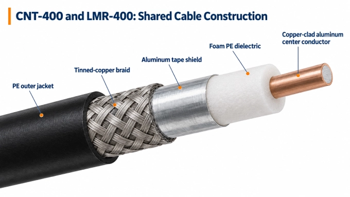
Both cables use a copper-clad aluminum center conductor, foam polyethylene dielectric, aluminum-tape shield, and tinned-copper braid. The center conductor carries the signal; the dielectric controls conductor spacing and contributes to impedance and velocity factor; the foil provides continuous shielding; and the braid supports the RF return path, connector termination, and mechanical strength.
CNT-400 lists 90 dB shielding effectiveness, while LMR-400 specifies greater than 90 dB. This wording does not establish a meaningful advantage without comparable test methods, frequencies, terminations, and acceptance criteria. Braid coverage is also not equivalent to shielding effectiveness: coverage describes braid geometry, while shielding effectiveness measures the performance of the complete shield structure.
Shielding effectiveness is also not evidence of low passive intermodulation. For cellular, DAS, or other PIM-sensitive installations, request a defined PIM limit with its test frequency, power level, connector configuration, and measurement method.
Can CNT-400 and LMR-400 Use the Same Connectors?
Their matching nominal diameter does not guarantee that CNT-400 and LMR-400 can use the same connector. Before substituting either cable, check whether the connector manufacturer explicitly lists the exact cable type as compatible.
Connector selection should account for:
Center-conductor diameter and attachment method
Dielectric and shield diameters
Braid thickness and ferrule or clamp dimensions
Required strip lengths and cable-preparation tools
Crimp-die or tightening requirements
Strain-relief and environmental-sealing provisions
A connector may fit the cable physically but still produce an incorrect pin position, weak braid retention, poor shield contact, or inadequate sealing. These faults can increase insertion loss and VSWR or reduce pull strength, shielding, and moisture resistance.
CNT-400 vs LMR-400: Bend Radius and Environmental Requirements
CNT-400 and LMR-400 have the same published minimum radius for a single installation bend, but routing requirements and environmental suitability depend on how the cable will be installed and used.
Fixed Routing vs Repeated Movement
Both standard cables specify a minimum installation bend radius of 25.4 mm. This is the tightest permitted installation bend, not a recommended routing target. Use a larger radius where space permits, especially near connectors, and support the cable so its weight, routing tension, or vibration does not load the termination.
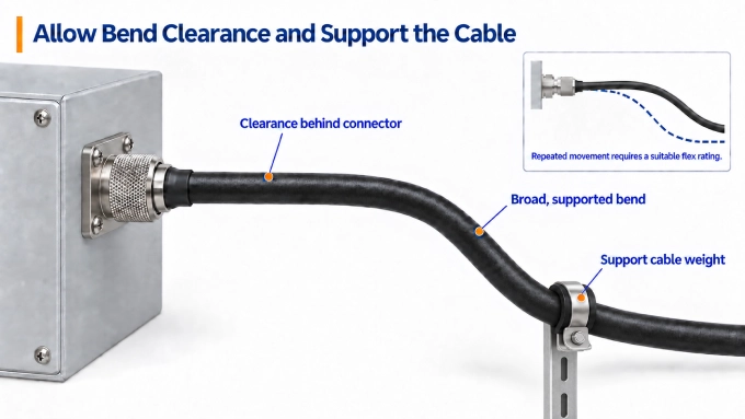
LMR-400 also lists a repeated-bend radius of 101.6 mm. CNT-400 product specifications do not include an equivalent repeated-flex value, so the standard cables cannot be compared numerically for dynamic service. Applications involving regular movement, such as hinged equipment, positioners, or mobile machinery, should use a cable explicitly rated for repeated flexing and be evaluated against documented bend-life and flex-radius requirements. Compare flexible variants separately because changes in conductor and jacket construction may also affect attenuation and connector compatibility.
Match the Jacket and Cable Variant to the Installation
The standard CNT-400 and LMR-400 specifications list installation and operating temperatures from −40°C to +85°C and storage temperatures from −70°C to +85°C. These limits do not establish compliance with every outdoor, indoor, or buried-installation requirement.
For outdoor routes, verify UV resistance, moisture protection, connector sealing, and the temperature range expected in direct sunlight. Wet locations and direct burial require particular attention: an outdoor-rated jacket alone does not necessarily prevent water from migrating along the braid if the jacket is damaged. Buried or persistently wet routes should use a documented water-blocked or direct-burial version.
Indoor installations may require fire-retardant, low-smoke, or halogen-free materials under the applicable building, transport, or safety code. Do not assume the standard PE jacket meets those requirements just because the cable operates within the required temperature range.
CNT-400 vs LMR-400: Velocity Factor
CNT-400 has a nominal velocity factor of 85%, compared with 84% for LMR-400. The difference produces a small change in propagation delay and electrical length for equal physical cable lengths. It is unlikely to determine selection for ordinary fixed feeds but may matter in phased arrays, delay lines, timing networks, and phase-matched assemblies.
When substituting one cable in a delay- or phase-sensitive system, verify electrical length, velocity-factor tolerance, phase matching, and stability over temperature or flexing. A higher velocity factor does not inherently indicate lower attenuation or better phase stability.
Which Cable Should You Choose for Your Application?
For most fixed installations, electrical specifications alone do not determine the better cable. Selection depends on whether the exact cable and finished assembly satisfy the application’s loss, power, mechanical, environmental, and documentation requirements.
Before ordering, provide or verify:
Manufacturer, cable part number, and complete suffix
Operating frequency band and finished length
Connector interfaces and orientations
Maximum insertion loss and return-loss requirements
Average power, peak power, duty cycle, and VSWR
Routing space, movement, and environmental conditions
Quantity, lead time, traceability, and required test documentation
These requirements provide the basis for selecting or specifying custom cable assemblies. If both cables satisfy them, procurement factors such as price, availability, approved-vendor status, tooling, and documentation may reasonably determine the final choice.
FAQ
Discussion (0)
Be the first to comment.