Microwave Connector Vibration Resistance: What RF Engineers Need to Know


Microwave connector vibration resistance depends on more than whether the connector remains physically mated. Vibration can loosen the coupling, wear its center and outer contacts through micromotion, or fatigue its mount and cable termination. These changes can cause intermittent RF faults or disturb impedance, increasing VSWR and reducing return loss even while the connector appears secure.
How Vibration Affects Microwave Connectors
Vibration and repeated motion can affect the mating interface, contact surfaces, connector body, mounting hardware, and cable termination in different ways. The following failure modes help identify what to inspect and which design features and installation practices require attention.
1. Connector Loosening and Loss of Retention
Cyclic loading can cause movement between mating halves. In susceptible threaded connections, that movement may reduce joint security and allow the coupling nut to back off. A connector may gradually lose clamping force while remaining mated, become partly disengaged, or separate completely.
Retention can refer to different parts of the assembly. The force required to separate mating halves is distinct from the retention of a coupling component on the connector body, a contact within the connector, or a cable within its termination. A rating for one relationship does not establish the strength of the others.
2. Fretting and Deteriorating Contact Integrity
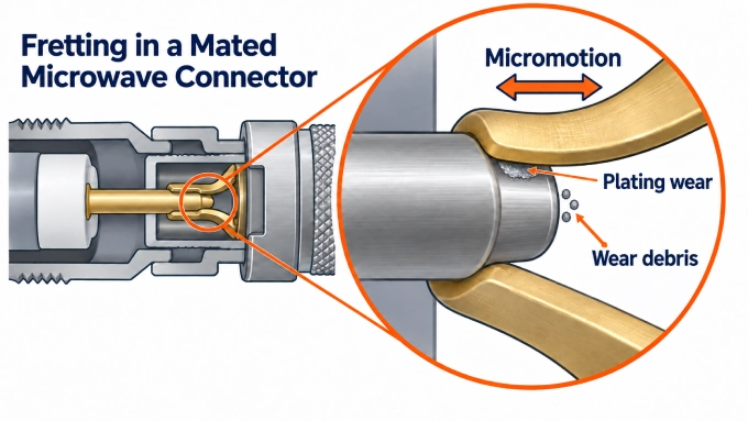
Fretting is wear caused by repeated small movements between contacting surfaces. It can affect the center-contact interface and the outer-conductor interface while the connector still appears fully mated.
Micromotion can wear the contact finish and leave debris that interferes with metallic contact. If wear exposes underlying material, oxidation may contribute to further degradation. The outcome depends on the finish, materials, contact pressure, movement, and environment; gold plating itself should not be described as forming an insulating oxide. Research on vibration-induced fretting in RF connectors demonstrates that contact wear can develop without visible separation.
Mechanical Instability and Fatigue at Mounts and Terminations
Vibration also loads the parts supporting the interface: connector bodies, internal contact supports, solder joints, crimped terminations, and PCB or panel attachments. Unsupported cable mass and stiff routing can exert leverage on these points. Resonance in the cable or mounting structure can increase local movement and accelerate fatigue.
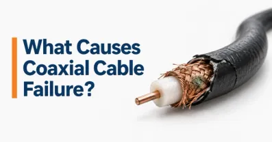
Damage at the mating interface must be distinguished from a cracked PCB joint, weakened cable termination, or failure in the adjacent cable. Those related RF cable failure mechanisms call for inspection beyond the connector’s mating faces.
How Does Vibration Affect VSWR, Return Loss, and Signal Stability?
A connector can remain mechanically engaged while its RF performance changes. Some effects appear only as the assembly moves; others persist after contact wear or mechanical damage.
Impedance Changes and Increased Reflections
A microwave connection depends on controlled conductor geometry and reliable center- and outer-contact engagement. Movement at the mating interface can disturb that geometry or the outer-conductor return path, creating an impedance discontinuity. The connector-to-cable and connector-to-device transitions also contribute to the assembly’s match.
A worse match produces higher VSWR and lower positive return loss. At a given frequency, a change from 20 dB to 10 dB return loss raises VSWR from approximately 1.22:1 to 1.92:1. On a display showing S11 magnitude in dB, the same change appears as −20 dB to −10 dB: the trace becomes less negative. Because reflections vary with frequency, performance must remain within limits across the required operating band, not just at one test frequency.
Intermittent RF Changes Versus Permanent Degradation
During vibration, contact movement can cause brief signal interruptions or fluctuations in insertion loss and reflections. The connection may appear normal again when motion stops. Wear, deformation, or a damaged termination can instead leave a measurable change after exposure; intermittent and lasting effects can also occur together.
Movement may introduce phase variation in phase-sensitive systems. Research on vibrating RF contacts found changes in microwave transmission and phase-noise behavior associated with fretting. Passing a DC continuity check establishes a conducting path under the conditions of that check, but does not establish stable microwave matching, loss, or phase performance.
Which Specifications Define Microwave Connector Vibration Resistance?
A vibration rating is useful only when the applied loading, installed configuration, and pass criteria are known. Engineers should look for three sets of information in a datasheet or qualification report: the vibration profile, the connector’s mechanical and contact specifications, and the RF limits measured during and after exposure.
Vibration Profile, Severity, and Exposure
Record the conditions behind any published claim:
Type and frequency range: Was the test sinusoidal, random, or combined? The vibration frequencies describe mechanical excitation in hertz, not the connector’s RF operating band.
Sinusoidal severity: Identify acceleration and displacement limits, including whether acceleration is stated as peak or RMS and displacement as single amplitude or peak-to-peak travel.
Random severity: Check the power spectral density in g²/Hz, its shape across the specified frequency range, and the overall acceleration in Grms.
Exposure: Note the duration and direction of each axis, plus sweep rates, sweeps, or cycles where applicable.
Installed configuration: Identify the mating counterpart, mount, cable routing and support, and whether the connection was operating or monitored during the test.
A statement such as “20 g” omits the loading profile, amplitude convention, and exposure. “MIL-STD tested” is similarly incomplete: MIL-STD-202 Method 204 addresses high-frequency sinusoidal vibration, while Method 214 addresses random vibration. The method and its condition must be identified before the result can be interpreted.
For example, a manufacturer might list Method 204, Condition B, while another manufacturer lists Method 204, Condition D. The different conditions show why the test designation matters; they do not, by themselves, establish which connector system will perform better in a given installation. Both manufacturers may describe their series-level specifications as typical, so the particular part datasheet and test report remain essential.
Retention, Contact, and Durability Specifications
Mechanical ratings describe different parts of the connection. Read each one together with its test condition and the component to which it applies.
Static pull-off strength indicates resistance to a defined separating load, and mating durability indicates performance after a defined number of cycles. Neither shows whether contacts remain stable under repeated small movements during vibration. Likewise, a contact-resistance limit measured at rest cannot replace measurements made while the connection is moving.
RF Performance Limits During and After Vibration
A qualification report should state maximum VSWR or minimum positive return loss across the required RF band, along with insertion-loss limits and, for phase-sensitive systems, allowable phase change. Check whether these are absolute pass limits, permitted changes from the initial measurement, or both.
Timing is part of the specification. The report should identify which limits apply before, during, after, or throughout vibration. If brief electrical interruptions are prohibited, it must define what counts as an interruption, the longest permitted event, and a monitoring response time short enough to detect it. An acceptable measurement after the test cannot establish that the RF path stayed within limits while the connector was moving.
How to Choose and Install a Microwave Connector for High Vibration
Begin with the required RF band and vibration environment, then account for space, mounting arrangement, temperature range, and access for mating and maintenance. These constraints determine which coupling designs can be installed correctly and how the connector and cable can be supported.
Select the Coupling Mechanism for the Installation
Threaded coupling can secure a connection when the mating hardware is accessible and installed as specified. A push-on interface may suit compact or blind-mate arrangements, but its detent option and allowable movement must match the installation. Positive locks add a distinct means of preventing accidental separation.
Control Cable Loading and Support the Connector Mount
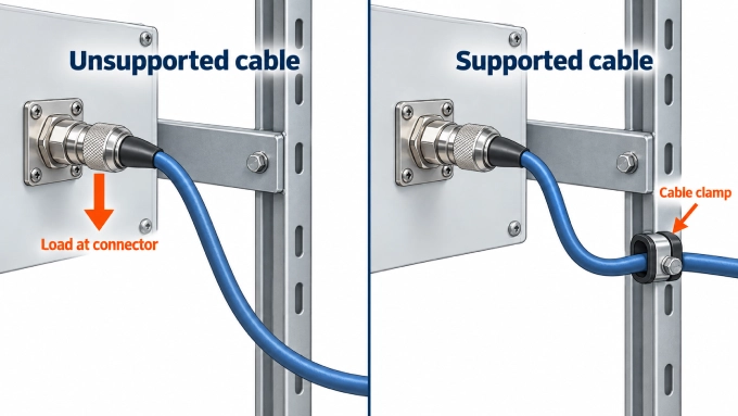
Cable mass, stiffness, and unsupported length determine how much force vibration transfers to the connector. Route the cable within its specified bend radius and support it with suitable clamps or strain relief so its weight and motion do not load the mating interface or termination. Check that a panel mount or PCB attachment can withstand the resulting forces as well.
If connected structures move relative to one another, a supported flexible section can accommodate that motion without forcing it into the connector. For floating or blind-mate interfaces, confirm that the contacts remain properly engaged across the expected board spacing, alignment tolerances, and movement range.
These choices are best made together for a custom RF cable assembly: cable flexibility, connector termination, routing, and strain relief all affect the installed connection.
Apply the Specified Torque and Confirm Full Engagement
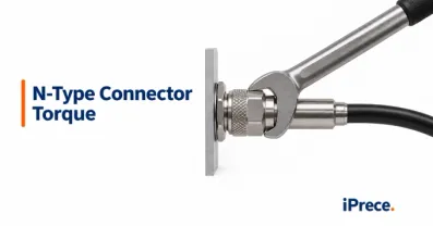
For threaded connectors, follow the mating instructions and torque value for the exact parts. Use the specified torque wrench on the coupling nut, and restrain the connector body or cable where required so tightening does not twist the termination. Manufacturer-specific SMA connector torque guidance is especially useful when establishing an assembly procedure.
Confirm that mating halves are fully seated and that any positive lock is engaged according to its instructions. Tightening beyond the specified torque can damage the interface rather than improve vibration resistance. Use a secondary locking measure only when the connector design supports it and the assembly procedure approves it.
How to Verify RF Connector Vibration Performance
Test the connector as part of a representative mated installation. Verification needs to capture faults that occur while the assembly moves, as well as damage or performance changes that remain afterward.
Choose the Applicable Test Method and Configuration
The program’s environment and qualification requirements determine the method:
MIL-STD-202 Method 204 tests components under high-frequency sinusoidal vibration.
MIL-STD-202 Method 214 tests components under random vibration.
MIL-STD-810H Method 514.8 supports vibration evaluation tailored to the equipment’s intended environment; MIL-STD-810 does not prescribe one universal test profile.
RTCA DO-160 provides environmental test procedures for airborne equipment. Use the revision and vibration category required by the program.
A standard citation must be accompanied by its test condition or profile, exposure, specimen configuration, and acceptance limits. Mate the tested connector to representative hardware, and reproduce the intended mount, cable routing, and cable support. Check vibration input near the relevant mounting points: a fixture that amplifies or suppresses motion can change the loading the connector actually experiences.
Measure Performance Before, During, and After Exposure
Before: Record the installed condition and establish baseline contact-resistance and RF measurements across the required band.
During: Monitor electrical interruptions and the RF quantities that must remain stable, using a response time appropriate to the shortest fault of concern.
After: Repeat the baseline measurements and inspect for coupling back-off, contact wear, cracks, and termination damage.
A conventional swept VNA measurement samples frequencies at different times and may miss a brief fault between sweeps. Where transient RF changes matter, use suitable time-resolved monitoring at critical frequencies alongside the required band measurements. Continuity monitoring can detect interruptions, but it should complement the RF measurements rather than stand in for them. Secure and account for movement of the measurement cables so their own changes are not attributed to the connector.
Review the Evidence Before Approving the Connector
The report should identify the tested part numbers and mating counterparts; mounting and cable configuration; applied profile, axes, duration, and deviations; monitoring methods and pass limits; and any observed interruptions, RF changes, or physical damage.
A pass demonstrates performance under those defined conditions. It does not establish the installed assembly’s service life under every vibration environment.
FAQ
Discussion (0)
Be the first to comment.