Radio Frequency Interference (RFI): How to Find it and Fix it

Radio frequency interference (RFI) is unwanted RF energy that degrades a system’s intended signal or operation. Preventing it requires controlling emissions, limiting the paths that carry unwanted energy into sensitive circuits, and giving receivers enough selectivity and isolation to tolerate what remains. Engineers can do this through frequency planning, well-placed filters, reliable grounding and shielding, deliberate cable routing, and sound connector interfaces.
When interference is already present, measure the affected signal and trace the source and coupling path before choosing a fix. The result should be judged against the system’s performance limits: lower interference must translate into acceptable sensitivity, signal quality, or other relevant operating metrics.
How to Detect and Measure RF Interference
Start with the receiver or circuit showing the fault. Establish a reference condition, choose a suitable measurement setup, then detect and characterize unwanted RF energy in frequency and time.
A. Establish the Symptom and a Reference Condition
Record the affected frequency, operating mode, enabled transmitters, and timing of the fault. Compare the relevant metric—receiver sensitivity, noise floor, EVM, BER, or an unexpected spur—with a known-good condition, changing one operating variable at a time.
B. Choose Equipment for RF Interference Detection
Engineers typically detect RF interference with a spectrum analyzer or suitable RF receiver connected to an antenna, probe, or RF measurement point. Choose the setup for the suspected signal’s frequency, level, and duration. A product labeled “RFI detector” is useful only if its capabilities match the investigation.
Investigation | Suitable equipment | Main role |
Continuous or slowly changing interference | Spectrum analyzer with an appropriate antenna or RF connection | Display signal levels and spectral structure across the frequencies of interest. |
Brief bursts or intermittent signals | Real-time spectrum analyzer or capture-capable RF receiver | Capture events that a conventional sweep may miss. |
Extended observation | Monitoring receiver or analyzer with logging and triggers | Record activity when interference occurs infrequently or requires unattended monitoring. |
Circuit, enclosure, or cable investigation | Analyzer with near-field probes or an RF current probe | Examine local emissions or RF currents on cables. |
Field investigation | Portable or handheld analyzer/receiver with a suitable antenna | Support measurements around an installation; add a directional antenna and position/bearing logging when source location is required. |
C. Measure and Characterize the Interference in Frequency and Time
Record the interference’s frequency, level, bandwidth, and time behavior at a defined measurement point. These observations establish the signature needed for the subsequent source investigation.
Define the measurement point and frequency span. Identify the reference plane; for example, the receiver input or antenna connection, and examine the affected band together with relevant surrounding frequencies. Include suspected out-of-band blockers where appropriate.
Check the trace before interpreting it. Set resolution bandwidth (RBW), input attenuation, and gain to reveal the suspected interference without overloading the instrument. Narrower RBW can separate nearby signals and lower displayed broadband noise, but may lengthen a swept measurement. Establish whether the instrument’s own noise floor obscures the energy being investigated. With strong signals present, repeat the measurement using increased input attenuation to check for analyzer-generated spurs or distortion.
Characterize the spectrum and report the level correctly. Identify isolated tones, harmonic families, broadband energy, or other spectral structures. Record their frequencies, bandwidths, and levels. A marker reading at one frequency differs from channel power integrated across a specified bandwidth.
Capture time behavior. Examine burst duration, repetition, frequency drift, hopping, and periods of inactivity. Max hold retains the highest observed levels; a spectrogram adds their progression over time. Triggered capture can preserve an event for detailed analysis.
Spectral patterns can suggest possible causes, but they do not uniquely identify a device. Confirming the source and coupling path requires the investigation that follows.
How to Locate the RF Interference Source and Identify Its Coupling Path
Compare interference with the receiver’s antenna connected and its input appropriately terminated. A reduction suggests an antenna-side route; interference that persists warrants investigation of internal sources, enclosure leakage, or conducted coupling through power, control, and shared-return paths. Treat this as evidence, since changing the termination can also change coupling conditions.
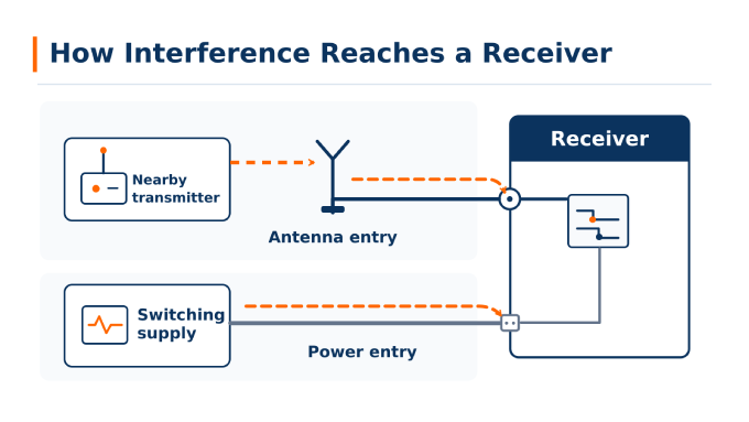
Investigate suspected sources within the system or installation using the local procedure below. If the recorded signal appears to originate beyond the installation, proceed to external hunting.
Trace a Source Within the System or Installation
Change one suspected source or interconnect at a time. Disable or substitute suspected sources and interconnects individually, tracking both the interference signature and system performance. Restore the original configuration between tests where practical. Substituting an interconnect may change the coupling path without identifying the device generating the unwanted energy.
Test the operating conditions associated with the fault. Compare transmitter, converter, or digital activity with the recorded event. Run suspected transmitters individually and then together to establish whether the interference depends on simultaneous operation. For converters or digital circuits, test relevant loads or operating modes while keeping other conditions consistent.
Trace emissions and cable currents. Use near-field probes to locate emissions around circuits and enclosure seams, and suitable current probes to investigate unwanted cable currents. Follow the previously recorded frequency-and-time signature so that an unrelated emission does not divert the investigation.
Confirm the source-to-fault relationship. Repeat a suspected source change to check whether its effect is reproducible. Establish that the improvement is associated with the unwanted energy rather than a change to the wanted signal path. A convincing diagnosis connects source activity, coupling, and the observed performance loss; an emission hotspot alone is insufficient.
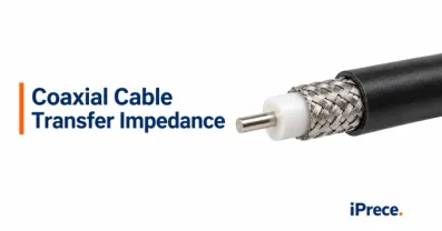
Differential-mode interference travels between conductors. Common-mode current flows on conductors together relative to their surroundings. During normal RF signal transmission through coaxial cable, the wanted signal propagates between the center and outer conductors. Unwanted common-mode current can flow on the outer surface, allowing the cable to couple interference even when its intended signal path remains functional.
Hunt an External Source With a Directional Antenna
Follow the recorded interference signature. Tune to the signal being investigated and check its spectral and timing characteristics before taking bearings. In a crowded environment, the strongest received signal may belong to another transmitter. Continue checking the signature as you move.
Prepare the directional antenna. Use an antenna whose operating range and directional pattern suit the interference frequency. Set its polarization appropriately and consult its documented peak or null behavior. Position it so nearby structures and the operator’s body introduce as little disturbance as practical.
Record a position and bearing. Rotate the antenna while observing the selected signal. Record the bearing associated with its documented directional response, your position, and the observation time. Use a consistent compass reference. As the signal becomes stronger nearby, additional attenuation may help preserve useful directional discrimination.
Repeat from separated positions. Plot further bearings to narrow the likely source area. Reflections, obstructions, and front-to-back ambiguity can produce misleading directions, so investigate inconsistent results from another position. Signal-strength mapping plots levels across locations; bearing-based triangulation combines directions. Neither should be treated as an exact position without corroboration.
Corroborate the suspected source. Make closer observations where access permits, checking that the signal still matches the recorded interference. Where appropriate, coordinate a controlled operating test with the source’s operator. A plausible bearing intersection identifies an area to investigate; confirmation establishes which source is responsible.
Automated angle-of-arrival (AoA) systems estimate the direction from which a signal arrives. One bearing does not establish a unique position. Synchronized time-difference-of-arrival (TDoA) systems compare signal arrival times at separated receivers to estimate location. These methods can support persistent monitoring or investigations where manual bearings are difficult to obtain.
How to Fix RF Interference
RFI mitigation can act on the source, the coupling path, or the affected circuit. Use the confirmed mechanism to select a starting method below. Where appropriate and within your control, repair or replace the source, relocate it, or coordinate its operation. Combine measures when one does not provide enough suppression.
Confirmed problem | Starting methods | Main limitation |
Co-channel interference entering through the antenna | Coordinate frequency or timing; improve antenna isolation | A filter cannot separate fully overlapping signals. |
Out-of-band blocker reaching the receiver | Add rejection before vulnerable stages; improve isolation or gain control | Filtering after overload cannot undo distortion. |
Noise conducted on power or control wiring | Suppress the source; filter the interface; improve return paths | Shielding alone leaves the wiring path. |
Coupling between circuits inside the system | Increase separation; partition circuits; control returns or add local shielding | An outer enclosure may leave internal coupling intact. |
Unwanted common-mode current on a cable | Improve bonding and routing; apply suitable common-mode suppression | A choke around coax does not remove interference carried inside it. |
Passive intermodulation at a connection | Repair or replace the nonlinear contact; use suitable low-PIM hardware | Good matching does not establish acceptable PIM. |
1. Prevent RF Interference Through Frequency Planning and System Isolation
Frequency planning and isolation determine how much unwanted energy can reach a sensitive path before filtering, shielding, or other component-level measures are chosen. Addressing conflicts at this stage is especially valuable when transmitters and receivers must operate at the same time.
List the transmit and receive bands, local oscillator (LO) and intermediate frequencies (IF), sampling and digital clocks, and switching-converter frequencies for every relevant operating mode. Then check whether harmonics, intermodulation products, mixer responses, or sampling aliases can land in a sensitive band. Perform the check across the tuning range rather than at one nominal frequency.
Separate high-power transmit paths from sensitive receivers, LOs, clocks, and switching circuits when arranging antennas, modules, and boards. For antennas, evaluate spacing together with pattern, orientation, and polarization: a change that reduces pickup from an aggressor may also weaken the wanted link. Measure isolation in the installed geometry, where nearby structures and reflections can change the result.
Define the maximum tolerable interference at the receiver input, then allocate suppression across the relevant path using consistent frequencies and reference planes.A +30 dBm carrier limited to −70 dBm requires 100 dB of suppression; adding 10 dB of margin gives a 110 dB target. Check for coupling paths that bypass the intended isolation or filtering.
Budget transmitter noise within the receive band separately: a receive-band filter passes that noise along with the wanted signal.
2. Use Filtering Where It Can Prevent Interference
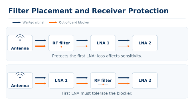
Filtering is useful when unwanted energy can be separated from the wanted signal by frequency or by how it flows through a connection. The filter’s location matters as much as its stated rejection: it must limit interference before that energy disrupts a vulnerable stage.RF filters cannot separate a wanted signal from interference that fully overlaps it in frequency.
Match the filter to the frequencies that must pass and those that must be suppressed. A band-pass filter can reject signals outside a receiver’s operating band; a low-pass filter can suppress transmitter harmonics; a high-pass filter can reject unwanted energy below the wanted band. A notch filter is useful when a specific blocker must be attenuated without narrowing a broader passband. Where transmit and receive paths share an antenna, appropriate duplexing also helps limit transmitter energy reaching the receiver.
In receiver topologies with a preselector before the first low-noise amplifier (LNA), filtering can prevent blocker overload, but its passband loss can worsen sensitivity. Filtering between gain stages leaves the first LNA exposed. Choose placement from the receiver’s noise, gain, and linearity requirements: filtering after amplifier compression or ADC clipping cannot recover lost information.
On power and control connections, reduce noise at its source, provide local decoupling, and filter sensitive interfaces while preserving supply stability and intended signals.Match the component to the current path identified during diagnosis. A filter across or in the conductors can address differential-mode noise; a suitable common-mode choke or cable ferrite may impede common-mode current.
3. Control Grounding, Bonding, and RF Return Paths
Grounding reduces interference when it gives unwanted currents a controlled path that does not disturb sensitive signals. The design question is where currents flow at the frequencies of concern, rather than whether two points appear connected on a DC continuity check.
A signal reference provides the return path for a circuit’s intended current. Chassis bonding connects conductive structures so RF currents do not create large voltage differences across an enclosure or interface. Protective earth serves an electrical safety function.When switching or transmit currents share a return path with a sensitive receiver, shared impedance can develop a noise voltage. Keep returns short and reference structures continuous, avoiding narrow shared connections and reference-plane gaps. DC continuity does not establish low RF impedance, and star grounding is not a universal high-frequency remedy.
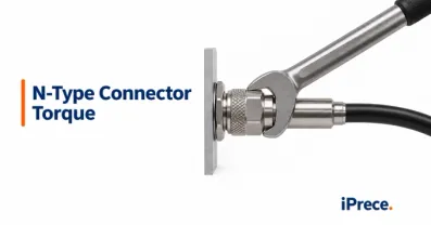
Provide low-inductance connections at connector shells, bulkheads, panels, and shield terminations. Where appropriate, use circumferential shield termination; a long pigtail can weaken high-frequency bonding.
4. Reduce RF Interference Through Enclosure Shielding
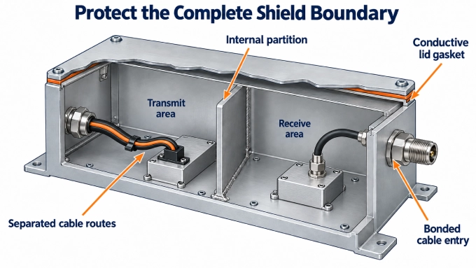
Shielding reduces interference that couples through electromagnetic fields. Its effectiveness depends on the complete boundary around the protected circuit or unwanted source, including every opening and connection through that boundary.
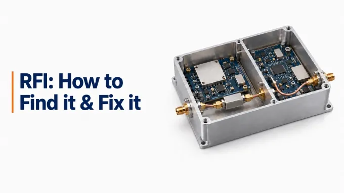
Use a local shield to contain a source, an internal partition to reduce coupling between circuits, or an enclosure to limit energy entering or leaving the system. Putting a transmitter and receiver inside the same metal box may leave their mutual coupling unresolved; separate compartments and controlled connections may be needed.
Inspect seams, gaskets, vents, and access panels; smaller openings become significant at microwave frequencies. Include connectors and cable entries in the shield boundary, applying the bonding and interface-filtering guidance above.
Use RF absorber material where a confirmed cavity resonance or reflected coupling path warrants it, selecting its frequency range and placement for that specific problem.
5. Maintain RF Cable Routing and Connector Integrity
Interconnects can carry interference between sections of an RF system, while damaged or poorly mated connections can create problems of their own. Routing and inspection should therefore address both coupling along the cable run and faults at its interfaces.
Separate low-level receive cables from transmit feeds, switching-power wiring, and noisy digital harnesses; minimize unnecessary parallel runs. Evaluate isolation in the installed geometry rather than relying on universal spacing or 90° crossings. Respect bend radius and support terminations against tension and movement.
Check that mating interfaces are compatible and that contacts are clean, undamaged, and fully engaged. A mismatch between the coaxial cable characteristic impedance and the connected interface can cause reflections.
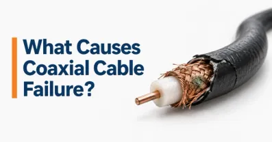
Inspect for signs of coaxial cable failure, including crushed sections, damaged outer conductors, or fatigued terminations. At connectors, contamination, corrosion, loose contact, or damaged mating surfaces can create a nonlinear junction. When two or more strong carriers pass through it, passive intermodulation (PIM) products may fall in a receive band.
When specifying custom RF cable assemblies, define the installed routing constraints, connector interfaces, insertion-loss limits, and shielding requirements together.
Verify the Fix and Prevent Recurrence
Confirm that the modified system meets its acceptance limits under representative interference conditions:
Repeat the original measurement: Use comparable settings, reference planes, geometry, and operating states. Confirm both interference reduction and improvement in the affected performance metric.
Check the wanted path: Measure added insertion loss and use VSWR and return loss to assess matching after RF-path changes. Repeat shielding or PIM tests where relevant; matching measurements alone do not validate them.
Exercise realistic conditions: Include simultaneous transmitters, tuning extremes, converter loads, and digital activity with cables installed and enclosures assembled. Add temperature, vibration, or movement tests where relevant, and observe enough cycles to capture intermittent faults.
Record acceptance: Document the change, configuration, measured results, and pass criteria. Include applicable emissions and immunity testing alongside checks representative of the intended operating environment.
FAQ
Discussion (0)
Be the first to comment.