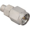
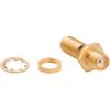

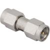
RF Adapter Types and Configurations
Adapter Types
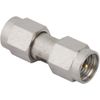
In-Series RF Adapter: Connects two interfaces within the same connector series, such as SMA-to-SMA.
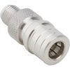
Between-Series RF Adapter: Connects interfaces from different connector series, such as SMA-to-TNC.
Orientation Types
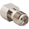
Straight Adapter: Provides a straight connection between RF interfaces for direct installations.
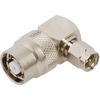
Right-Angle Adapter: Provides a 90-degree connection for installations with limited space or cable-routing constraints.
Tee Adapter: Provides a three-port connection for branching or connecting RF signal paths.
Mounting Types
Bulkhead Configuration: Allows an RF connection to pass through and be secured to a panel or equipment enclosure.
Panel-Mount Configuration: Allows an RF adapter to be mounted directly onto an equipment panel or chassis.
Connector Gender, Polarity & Orientation
Connector gender must be checked at both ends of the adapter. Standard and reverse-polarity interfaces also need to be distinguished where applicable. A matching connector family alone does not confirm that two interfaces can mate correctly.
When selecting a male RF adapter or RF adapter plug, confirm that the plug interface mates with the intended jack and that the center-contact arrangement matches the required standard or reverse-polarity configuration.
Straight adapters suit direct connections, while right-angle configurations can help where port access or installation clearance is limited. Bulkhead and panel-mount designs are relevant when the RF interface must pass through an enclosure or chassis; confirm the specific mounting construction before specifying the part.
RF Adapter Applications:
1. RF Test & Measurement
Connecting VNAs, spectrum analyzers, signal generators, and test fixtures to RF components or cable assemblies with different interfaces. Suitable RF connector adapters can simplify test setups, while connector savers help protect instrument ports from repeated mating cycles.
2. Telecommunications & 5G
Using RF coax adapters to connect compatible interfaces in telecommunications equipment, base stations, antennas, and wireless infrastructure. Connector series, impedance, operating frequency, and Low-PIM requirements should be checked where applicable.
3. Aerospace & Defense
Connecting RF and microwave components with the required interface and mounting configuration. Verify the exact connector combination, environmental limits, material requirements, and any applicable qualification records.
4. Broadcast & Video Systems
Using coaxial RF connector adapters in 75 Ω signal paths for compatible broadcast and video equipment. Verify that the selected connector interfaces are supported by the equipment, and confirm impedance and the required signal-path performance for the specific application.
5. Radar & Satellite Communications
Using RF-to-microwave adapters to connect RF subsystems, test equipment, and communications components with different interfaces. Frequency coverage, impedance matching, insertion loss, and mechanical reliability are important selection criteria.
Key Technical Details
RF adapter specifications depend on the connector combination, design, and intended operating conditions. Use the following criteria to compare available models and confirm the selected product against its own datasheet.
Specification | Key Details |
Nominal Impedance | 50 Ω is common in RF systems. Selected 75 Ω configurations are available for applications such as broadcast and video. Impedance must match the intended signal path. |
Frequency Range | The maximum specified frequency varies by adapter. As a family-level reference, iPrece lists standard TNC connector configurations up to 11 GHz and selected extended-range configurations up to 18 GHz. These figures must not be applied automatically to every TNC adapter. |
VSWR & Return Loss | Values depend on the exact product and specified frequency band. Compare the stated limits across the frequencies relevant to the application. |
Insertion Loss | Insertion loss is product- and frequency-dependent. Use the specified or measured value for the selected adapter rather than assuming a common value across a connector family. |
Power Handling | iPrece's published TNC connector-family information lists 316 W at 1 GHz and 25 °C. This is a family-level reference, not a universal rating for every adapter. Verify the selected adapter's documented rating and test conditions. |
Mating Durability | Repeated connection and disconnection can affect the mating interface. Check the applicable cycle rating for the exact product and interface design. |
Operating Temperature | The rated range depends on the selected part and its construction. Confirm the minimum and maximum temperatures in the product documentation. |
Mounting & Orientation | Available designs may include straight, right-angle, bulkhead, or panel-mount configurations. Verify that the required style is offered for the chosen connector combination. |
Materials & Finish | Body materials, contact materials, plating, and finishes vary by part. Select the construction appropriate to the electrical, mechanical, and environmental requirements. |
RF Performance & Quality Testing
An adapter must provide the required mechanical interface while meeting the electrical performance limits of the application. iPrece's published RF adapter information describes mechanical assessments for connector fit, torque requirements, and ruggedness, alongside RF performance checks that include insertion loss, VSWR, and return loss.
Additional evaluations, such as phase consistency and intermodulation testing, may be available upon request. Confirm the scope of testing, reporting, and traceability for the exact configuration before placing an order.
Where a connector interface is specified as compliant with a standard such as MIL-STD-348, verify which interface and product the claim covers. Interface compliance should not be treated as automatic qualification of every adapter or the complete RF system.
Rf Adapter Specifications & Ordering Requirements
Before ordering, match the selected part number and product documentation to the requirements of the system. Confirm:
The connector series, gender, polarity, and interface at both ends.
Required impedance and operating frequency range.
Insertion-loss, VSWR, return-loss, and power-handling requirements where applicable.
Mounting style, orientation, dimensions, and installation clearance.
Quantity and any environmental, qualification, testing, or documentation requirements.
For cable-to-equipment connections, an RF cable adapter or RF coaxial cable adapter must match the connector interfaces, impedance, and frequency rating required by the signal path.
For a quote request, provide the two interfaces that need to connect, the quantity, and the key operating and installation requirements. If the exact model is not yet known, share the application and system constraints so the available configurations can be narrowed down.
Use the quote option on the relevant product listing to request pricing, or contact iPrece to discuss the required configuration. Confirm any custom construction, additional testing, and documentation requirements for the specific order.