High Power Waveguide Dummy Loads: Selection Guide for RF and Microwave Systems

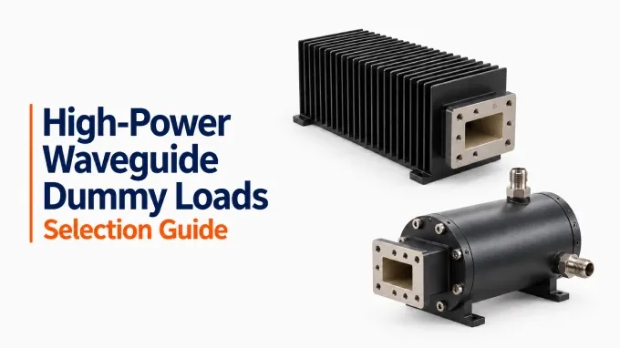
A high-power waveguide dummy load, also called a waveguide termination in microwave systems, is a matched one-port termination that safely absorbs and dissipates RF or microwave power while minimizing energy reflected toward the source. To select the right load, match its frequency band, waveguide and flange interface, VSWR, combined peak and average power capability, cooling requirements, and mechanical configuration to the system’s actual operating conditions.
Start by documenting the worst-case conditions the load will encounter—not merely the transmitter’s nominal output. Then compare those requirements with the load’s guaranteed specifications and the conditions under which its ratings apply.
High-Power Waveguide Terminations Compared with Medium- and Low-Power Loads
Characteristic | Low-power termination | Medium-power termination load | High-power termination load |
Absorbing element | Often a compact, tapered resistive or lossy dielectric element | A larger absorber with more heat-transfer capacity | Often a high-temperature refractory element; some designs use water itself as the absorber |
Cooling | Usually dissipates heat through its housing by natural convection | May use a larger housing, fins, or specified airflow | May require substantial fins, forced air, or a liquid-cooling circuit |
Installation | Typically compact, with few supporting services | Needs attention to clearance and airflow | May need coolant connections, flow and temperature monitoring, external support, and RF shutdown interlocks |
Main selection concern | Match and power rating at the operating frequency | Sustained heat removal as well as match | Combined peak and average power ratings under the actual pulse, cooling, and operating conditions |
These are typical design patterns, not fixed power categories: a manufacturer’s “high-power” rating depends on frequency, waveguide size, duty cycle, and cooling conditions.
What Power Rating Does Your Waveguide Dummy Load Need?
Base the rating on the maximum incident power at the load flange, accounting for the waveform, operating duration, and specified cooling conditions.
Start with the Power That Reaches the Load
Include transmitter output tolerance, overshoot, operating modes, and losses between the source and load. The required capacity also depends on the load’s position:
Main-output test load: receives approximately the transmitter’s full forward power.
Circulator-port load: receives reflected power, potentially approaching full transmitter output during severe mismatch. Check both the magnitude and duration of this exposure before protection acts.
High Power Waveguide Dummy Load Calculation
RF power handling has two principal constraints: average power determines heat-removal requirements, while peak power determines electric-field stress and breakdown risk. Both must be satisfied simultaneously.
For repetitive rectangular pulses:
Here, is the duty cycle, is pulse width, and is pulse repetition frequency. Energy per pulse is:
Check the complete waveform, not just the calculated average:
Pulse width and repetition rate: different combinations can produce the same average power but different pulse energies and transient heating.
Burst pattern: low long-term average power can conceal substantial heating during a burst.
Modulation: use actual average and peak-envelope power; rectangular-pulse equations do not represent every waveform.
Independent datasheet maxima may not apply together. A peak rating can assume negligible average power, while an average rating can assume CW operation. Verify the combined operating envelope or obtain supplier confirmation for the intended waveform.
Account for Derating, Test Duration, and Operating Margin
Confirm whether the rating permits continuous operation or requires limited on-time and cooling intervals. Apply the manufacturer’s derating for the actual temperature, cooling, mounting, and environmental conditions.
Pulse duty cycle and test scheduling are different: the former sets average power during a pulse train; the latter determines heating and recovery across operating periods. Specify both when relying on an intermittent rating.
Choose operating margin from output uncertainty, credible transients, fault exposure, and documented rating conditions. There is no universal requirement to select twice the transmitter power.
Match the Waveguide Load Frequency Range, Size, and Flange
Verify electrical coverage and mechanical compatibility separately: the correct waveguide designation alone does not establish either.
Specify the Full Operating Band and Waveguide Type
Include all operating channels, frequency-agile modes, tuning tolerances, and relevant test frequencies. Check the load’s rated bandwidth rather than assuming coverage from its WR designation.
Confirm the internal geometry—full-height, reduced-height, or another configuration—and intended propagation mode. Loads sharing a WR designation can have different absorber designs and guaranteed bandwidths.
Choose full-band coverage when the system needs frequency flexibility. An application-specific load may suit a fixed-frequency source and offer cost or packaging advantages, provided its guaranteed performance covers the required range.
Verify the Flange, Seal, and Installed Dimensions
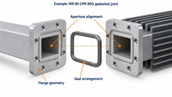
Compare the exact flange designation and mating drawings, including aperture dimensions, alignment features, contact surfaces, choke or groove geometry, and gasket arrangement. Similar bolt patterns do not guarantee a compatible RF joint.
For pressurized systems, verify the seal, guide-pressure rating, and allowable leakage. For installation, check:
Body dimensions and mounting orientation
Airflow clearance and coolant-hose access
Service access and external weight support
If a transition is needed, verify its bandwidth, VSWR, peak and average power capability, sealing, and mating interfaces. Mechanical adaptation does not establish electrical suitability.
What VSWR Is Acceptable for a Waveguide Termination Load?
There is no universal VSWR limit for every high-power waveguide dummy load. The acceptable value depends on how much reflected power the transmitter can tolerate, where its protection system trips, and how much mismatch uncertainty the test can permit. The selected load should remain below the system limit with allowance for flange joints, transitions, and measurement uncertainty.
Translate VSWR into Reflected Power
VSWR is easier to evaluate when converted into return loss and reflected-power percentage. The following values show the effect at 100 kW of incident power:
A VSWR of 1.20:1 may appear close to an ideal match, but it still returns approximately 826 W toward the source when incident power reaches 100 kW. If 100 kW is the peak pulse power, this is peak reflected power; if it is the average incident power, the reflected average is 826 W.
Select the limit from the transmitter manufacturer’s allowable load mismatch and the requirements of the test.
Check the Guarantee Across Frequency and Operating Conditions
Use a guaranteed maximum VSWR or minimum return loss across the required band. A typical value describes expected performance, not an acceptance limit.
Confirm the test reference plane and whether the specification applies only to low-power measurements or has been qualified at the intended power, temperature, and guide pressure. A good low-power result alone does not establish performance after the load heats up.
A specification at the load flange excludes external transitions and joints. Evaluate the assembled path at the transmitter’s reference plane, allowing for measurement uncertainty, and request supporting qualification data where operating conditions differ from the published test conditions.
Choose Cooling That Supports the Required Power and Duty Cycle
For a high-power waveguide termination operating continuously or through long pulse trains, liquid cooling can remove more heat than air cooling and support a higher sustained power rating. Choose it when the required heat dissipation exceeds a suitable air-cooled load’s rating, and verify the manufacturer’s combined peak and average power limits at the available coolant flow and inlet temperature.
Liquid vs Air Cooling for High Power Dummy Loads
Select cooling that can remove the absorbed average power throughout the intended operating period under the installation’s actual conditions.
Natural Convection and Forced-Air Cooling
As mentioned before, liquid cooling can offer superior heat dissipation. However, if you opt for natural convection or forced-air cooling, you must check the rating’s ambient temperature, mounting orientation, and ventilation requirements. Fins alone do not establish whether the specified power capacity assumes natural convection or forced air.
Where a fan is required, verify airflow at the installed load—not merely the fan’s free-air rating. Ducts, filters, obstructions, and recirculated hot air can reduce cooling.
The enclosure or facility must also remove the rejected heat: a load absorbing 10 kW releases approximately 10 kW into its surroundings.
Liquid-Cooled Loads and Direct Water Loads
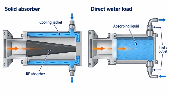
A liquid-cooled solid-absorber load transfers heat from a ceramic or refractory element to coolant. In a direct water load, the liquid itself absorbs RF energy. Use the approved coolant composition and purity for the specific design.
Verify:
Required flow and inlet-temperature range
Pressure drop and maximum coolant pressure
Outlet-temperature or temperature-rise limits
Cooling connections and installation provisions
The pump must deliver the required flow through the complete circuit, and the heat exchanger or chiller must remove the heat throughout the test. Liquid cooling does not remove operating limits: inadequate flow, warm coolant, contamination, or trapped air can reduce usable power.
Cooling Monitoring and RF Shutdown Requirements
Specify the flow, airflow, and temperature monitoring required by the load. Establish cooling before enabling RF, and connect cooling faults to the appropriate RF inhibit or shutdown function.
Do not assume the load can survive a cooling interruption. Obtain any documented survival interval at the intended power and initial temperature, then verify that the total detection and RF shutdown time is shorter.
Provide post-run cooling where required to remove stored heat. Confirm which sensors and interlocks are included with the load and which the system must supply.
Match the Waveguide Termination to the Application and Complete RF Path
The application determines whether load selection is dominated by sustained heating, pulse capability, reflected-power faults, or measurement requirements.
In synchronization or phase-alignment testing, the dummy load provides a controlled termination where the architecture requires one. It does not synchronize the system; frequency, phase, and timing alignment come from the reference source, distribution network, and control system.
Check Interfaces, Sampling Connections, and Environmental Requirements
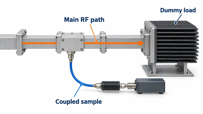
Verify switches, couplers, windows, and transitions against the path’s frequency range, peak and average power, and fault exposure. No component should be assumed suitable because the dummy load is adequately rated.
Where relevant, confirm guide pressure, gas condition, altitude, or vacuum compatibility. Waveguide gas pressure applies to the RF enclosure; coolant pressure applies to the fluid circuit. Their ratings are not interchangeable.
Coaxial sample ports carry coupled monitoring signals, not the main waveguide power. Calculate their peak and average output from transmitter power and coupling, including any added attenuation. Select custom RF cable assemblies for those levels, operating frequency, connectors, loss, and phase stability where needed. Check maximum RF voltage at coaxial interfaces as well as instrument input limits.
Selection factor | System information needed | What to verify on the load |
Frequency range | Lowest and highest operating frequencies | Coverage across the entire required band |
Power | Maximum peak and average incident power | Both ratings apply together under stated conditions |
Pulse profile | Pulse width, PRF, duty cycle, and test duration | Suitability for the actual pulse pattern |
RF match | Maximum VSWR or minimum return loss | Guaranteed limit across the required band |
Waveguide | Size, geometry, and operating mode | Matching internal dimensions and waveguide type |
Flange and sealing | Flange type, gasket, and pressurization | Exact mating flange, seal, and pressure rating |
Cooling | Airflow, coolant flow, temperatures, and ambient conditions | Rated power under the available cooling conditions |
Installation | Space, orientation, support, and protection needs | Dimensions, mounting, sensors, and interlocks |
Worked Example: Selecting a Load for a Pulsed Microwave Transmitter
Consider a hypothetical 9.5 GHz transmitter test with these requirements:
WR90 interface with UG-39/U cover flange
100 kW peak power
10 µs rectangular pulses at 1 kHz
Maximum load VSWR of 1.20:1
Continuous pulse train for 30 minutes
Available coolant: at 25°C inlet temperature
Using the pulse relationships established earlier:
Assume all three hypothetical candidates cover 9.5 GHz and meet the flange, mounting, and VSWR requirements.
For Candidate C, assume the supplier’s cooling requirements are compatible with the available flow and temperature, and the facility can sustain the required flow and heat rejection. Selection still requires confirmation that the load supports 100 kW peak and 1 kW average simultaneously for the stated pulse profile and test duration.
Doubling pulse width to 20 µs raises duty cycle to 2%, average power to 2 kW, and pulse energy to 2 J. Peak power remains unchanged, but Candidate C’s 1.5 kW average rating is no longer sufficient.
FAQ
Discussion (0)
Be the first to comment.