What Is an RG Cable? Applications & Comparison Guide

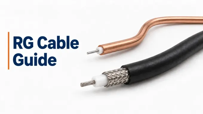
RG cables are coaxial transmission lines identified by legacy RG designations. They carry signals between RF equipment, antennas, and other system components. A center conductor runs along the cable’s axis, separated from a surrounding outer conductor by an insulating dielectric. The outer conductor provides the signal’s return path and electromagnetic shielding.
RG stands for Radio Guide. The naming system originated in U.S. military RF cable standards during the World War II era. These designations later became widely used in commercial applications and remain familiar cable identifiers today.
RG Cable Naming Convention
RG names identify cable designs through a prefix and type number, sometimes followed by a revision letter and suffix. RG-58C/U illustrates the four elements of a complete designation:
Element | Meaning |
RG | Radio Guide—the legacy designation prefix. |
58 | The complete historical cable-type identifier. The individual digits “5” and “8” have no separate technical meanings. |
C | A revision or modification identifier for this cable type. Letters such as A, B, and C distinguish versions. |
/U | A legacy general-use suffix, described as “universal” or “general utility use.” It does not mean suitability for every application. |
Revision letters can distinguish meaningful construction changes. For example, the historical RG-58/U design used a solid center conductor, while RG-58A/U used a stranded center conductor. This does not mean that “A” always indicates a stranded conductor: the letter identifies a revision within that cable type, rather than a universal material code or quality grade.
RG Cable Types and Related Coaxial Families
Flexible, semi-rigid, rigid, and hardline describe construction and handling. The terms overlap, particularly rigid line and hardline, and the latter two also cover transmission lines outside the RG naming system.
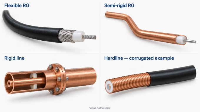
Flexible RG Cables: Flexible RG cables use a braided or foil-and-braid outer conductor around the dielectric, usually covered by a protective jacket. This construction allows bending for routing through equipment and connecting components.
Semi-Rigid RG Cables: Semi-rigid cables use a continuous metallic tube, commonly copper, as the outer conductor. Typical constructions have a PTFE dielectric. The cable holds its shape after forming, providing continuous shielding and a defined installed route. Assembly layout therefore requires planned bends and termination positions.
Rigid Coaxial Transmission Lines: Rigid coaxial lines use concentric metallic inner and outer conductors assembled into straight sections. Air-dielectric designs use insulating spacers to support the inner conductor. Joints and elbows establish the route, creating a fixed transmission-line installation.
Hardline Coaxial Cables: Hardline commonly uses a smoothwall or corrugated metallic outer conductor with foam or air dielectric. Corrugated designs accommodate controlled installation bending within their specified limits, allowing feeder routes to follow the installation layout.
Common RG Cable Comparisons: Which Differences Matter?
RG6, RG59, and RG11 commonly serve 75 Ω paths; the remaining pairs below commonly serve 50 Ω RF and microwave systems. The comparisons describe representative tendencies. Compare candidate constructions at the same frequency and length.
RG6 vs RG59
RG6 generally favors broadband distribution when attenuation matters; RG59 can favor compact video or instrumentation paths. Representative RG6 designs have a larger center conductor and dielectric diameter, usually producing lower attenuation than comparable RG59 constructions. The tradeoff is a larger cable that needs more routing space.
Precision RG59 constructions also support digital video, so digital signaling alone does not justify switching to RG6. Shielding depends on the version: both types can use foil-and-braid, while RG6 also commonly comes with additional shielding layers.
RG6 vs RG11
RG11 becomes useful when a 75 Ω distribution backbone or longer path needs lower attenuation than the candidate RG6 can provide. Its larger conductor and dielectric geometry generally reduce loss per unit length, leaving more of the system’s loss allowance available for other components.
That larger construction occupies more conduit and enclosure space, is generally stiffer, and typically requires a larger bend radius. Connectors and termination tooling must also suit its dimensions. Choose RG6 when it meets the loss allowance and routing is constrained; choose RG11 when the attenuation benefit justifies the larger cable, matching terminations, and installation space.
RG58 vs RG174
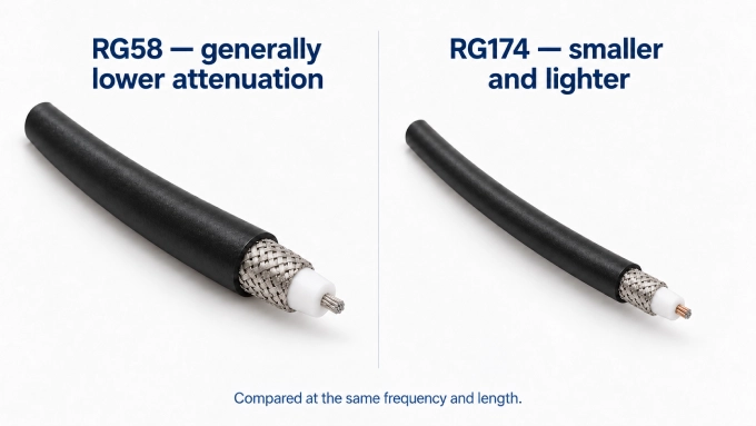
RG174 is a miniature, lightweight option that fits tight spaces and places less mechanical load on small embedded connectors. Compared with RG58, its smaller conductor geometry generally produces higher attenuation and lower power-handling capability. RG58 is larger and heavier, but usually provides more electrical margin.
Short antenna pigtails and embedded links can justify RG174 when the available loss and power margins permit it. For an external feeder or longer equipment connection, RG58 becomes more attractive as the additional RG174 loss accumulates. RG174 can serve transmitting paths when its power rating covers the operating conditions.
Other RG Cable Comparisons for RF and Microwave Requirements
Comparison | Primary decision | Requirement favoring each option |
Routing versus feeder performance | RG58 favors manageable equipment routing. Larger RG213 generally offers lower attenuation and greater power capability, favoring longer or higher-power RF feeders. | |
RG174 vs RG316 | Miniature cable materials and temperature | Representative RG174 uses polyethylene dielectric and a PVC jacket; RG316 uses PTFE dielectric and an FEP jacket. RG316 favors higher-temperature service. |
RG402 vs RG405 | Microwave assembly space versus electrical margin | The smaller RG405 fits tighter layouts. Larger RG402 generally offers lower attenuation and greater power capability but needs more routing space. |
Common RG Cable Applications
RG cables connect antennas, RF modules, test instruments, and video or broadband equipment. Their role varies with the signal path: delivering power, carrying weak received signals, linking circuit stages, or distributing signals between multiple locations.
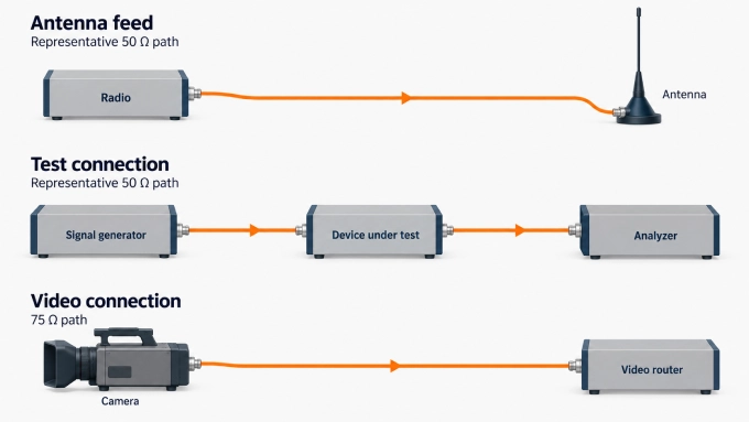
Radio and antenna connections. RG cable assemblies connect transceivers to antennas and link equipment such as amplifiers and antenna switches. In a transmitting system, feeder attenuation reduces the power reaching the antenna. In a receiving system, it reduces the signal reaching the receiver, making the connection particularly important when reception is already weak.
Embedded wireless and positioning systems. Short RG174 or RG316 assemblies connect wireless modules to antennas or enclosure-mounted connectors in devices such as GPS trackers and wireless gateways. This lets the designer position the antenna separately from the circuit board; for example, near an enclosure surface where reception is better.
Test and measurement. RG assemblies carry signals between instruments and a device under test: a signal generator supplies the stimulus, while an analyzer or power meter receives the output. They also serve laboratory patching and signal-monitoring connections. The interconnect forms part of the measurement path, so its electrical behavior contributes to the result.
Internal RF and microwave connections. Inside instruments and communications equipment, RG interconnects carry signals between circuit boards or modules, including oscillator and amplifier stages. Semi-rigid RG constructions are useful for fixed internal routes where the assembly layout calls for a formed, shielded connection.
Video transmission. Suitable 75 Ω RG assemblies connect cameras, patch panels, and video routers. These paths can carry analog video or serial digital interface (SDI) signals.
Broadband and satellite distribution. Cable television, cable-modem, and satellite-receiver installations use 75 Ω RG coax to carry RF signals between distribution equipment and receivers. Unlike a connection serving one narrow operating band, a broadband path may need to preserve multiple channels across a wide frequency range.
How to Select an RG Cable for Your Application
Establish impedance and operating band. Identify the nominal impedance of the equipment ports and intended transmission path. Use 50 ohm coaxial cable for a 50 Ω path, or an appropriate 75 Ω construction for a 75 Ω path. The connector interfaces must preserve the same nominal impedance.
Set installed length and permissible loss. Include routing and necessary service loops when calculating coaxial cable signal loss. For a uniform cable under matched conditions, use , where is frequency, is attenuation in , and is length in metres; the resulting cable loss is in dB.
Check average and peak power. Average power is limited by heat generated through conductor and dielectric losses; peak power is constrained principally by voltage stress. Apply the manufacturer’s rating conditions for frequency, ambient temperature, cooling, altitude, and expected VSWR. For pulsed or modulated operation, account for duty cycle and peak-to-average power ratio where applicable.
Apply mechanical constraints. Verify routing space, cable weight, minimum bend radius, and clearance around connector ends. Check the specified limits for installation bending and, where applicable, repeated movement. Define the motion range and required flex life for moving connections. Provide strain relief and supports to keep cable weight, pulls, and twisting loads away from the terminations.
Apply environmental and shielding requirements. Check temperature, UV exposure, moisture, direct burial, and chemicals. Verify direct-burial suitability separately from general outdoor suitability, and require the appropriate fire-performance classification for the installation. Include connector sealing where needed. Set shielding or isolation requirements across the operating band, considering nearby transmitters, sensitive receivers, and the completed shield termination.
How to Choose Connectors for Common RG Cables
Start with the equipment port: match the connector series, plug or jack configuration, polarity where relevant, and impedance. Then select a connector version designed to terminate the exact cable construction. For example, BNC connectors are available in both 50 Ω and 75 Ω versions; the interface name alone does not establish electrical compatibility.
These representative pairings provide a starting point:
RG cable examples | Common connector options | Typical connection |
RG58 | 50 Ω BNC or SMA | Laboratory patching and RF equipment connections. |
RG213 | 50 Ω N-type | Radio equipment and antenna feeders. |
RG174 / RG316 | SMA or MMCX | Antenna pigtails and compact RF modules. |
RG59 / RG6 | 75 Ω BNC | Video equipment and distribution connections. |
RG6 / RG11 | F-type | Broadband, television, and receiver distribution paths. |
RG402 / RG405 | SMA versions for the respective semi-rigid cable | Fixed microwave connections between modules. |
Check the connector’s compatibility list and assembly drawing against the cable’s center conductor, dielectric diameter, shield construction, and jacket diameter where applicable. Similar overall diameters do not establish equivalent fit: the center contact and outer-conductor termination must both suit the cable. Use the specified preparation dimensions and tooling for the chosen termination method.
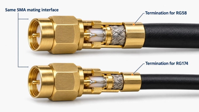
Next, verify frequency and power suitability for the selected connector configuration. A connector family’s highest rating does not apply automatically to every cable termination or right-angle version. Choose orientation and mounting arrangements that provide mating access and cable clearance, and confirm any required environmental sealing.
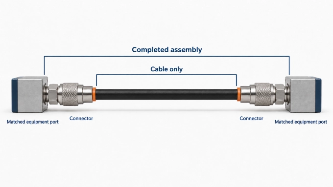
For custom RF cable assemblies, specify the finished length and connector orientations. Confirm the required insertion loss, return loss or VSWR, and any phase requirements for the completed assembly; compatible components alone do not establish its final performance.
FAQ
Discussion (0)
Be the first to comment.