RG58 vs RG213: Key Differences, Performance, and Applications

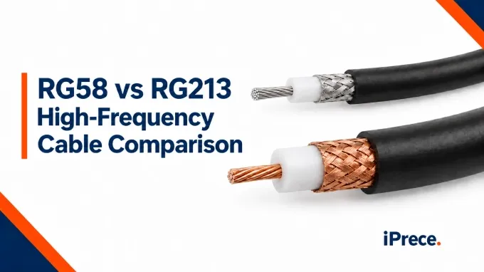
RG58 and RG213 are both 50-ohm coaxial cables used in RF systems, but their different constructions suit different performance and installation priorities. In custom RF cable assemblies, choosing between them affects routing, connector compatibility, insertion loss, and usable power. RG58 is smaller, lighter, and easier to route, while RG213 offers lower attenuation and greater power capability at the cost of roughly twice the diameter and four times the weight. The right choice depends on operating frequency, run length, power level, available space, and the specifications of the exact cable construction.
How Do RG58 and RG213 Construction Affect Routing and Flexibility?
RG58 is easier to route through confined equipment, vehicles, and dense cable paths. RG213 requires more clearance, greater bend space, and stronger mechanical support, but its larger conductors and dielectric provide the physical basis for lower attenuation and higher power capability.
This comparison uses the iPrece RG58C/U and RG213/U constructions linked in the table. The values apply to these specific products and should not be treated as universal specifications for every RG58 or RG213 cable. Verify the current product datasheet before final selection.
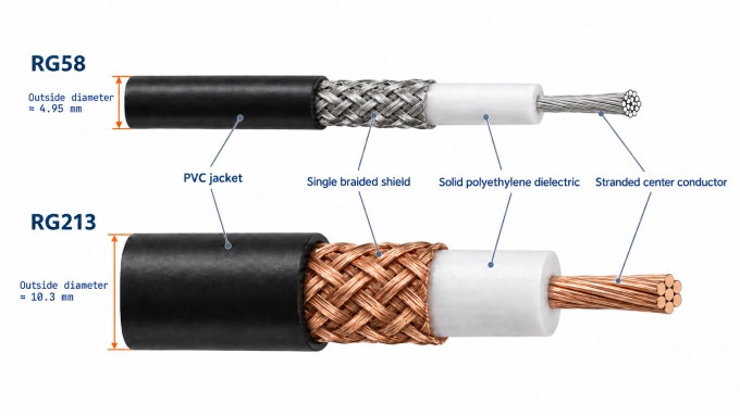
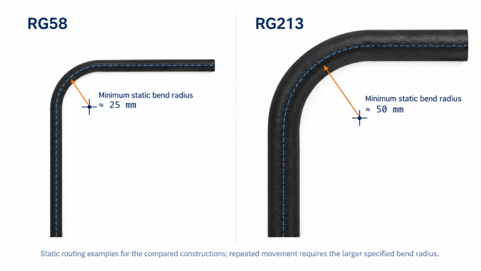
The smaller diameter and lower weight of RG58 reduce the force needed to position the cable and the load placed on connectors, panels, and mounting hardware. Its tighter bend requirements also make it more practical around enclosure corners and through restricted passages. A stranded center conductor helps both cable types tolerate bending, but it does not cancel the effect of RG213’s larger dielectric, braid, and jacket.
Neither cable should be bent below its specified radius. A static bend rating applies after installation, while the larger repeated-bending radius applies where the cable will be moved, repositioned, or exposed to vibration. Standard RG58 and RG213 constructions are flexible cables rather than continuous-motion cables; applications involving frequent flexing require a cable specifically rated for that duty.
RG58 vs RG213 Attenuation: Which Works at Your Frequency and Length?
RG213 has lower attenuation at each compared frequency, but run length determines whether that advantage matters. At 1 GHz, its nominal loss per meter is about 60% lower than RG58’s.
Published nominal attenuation for the specific iPrece RG58C/U and RG213/U products. These values are not universal ratings for every RG58 or RG213 construction. Verify the current product datasheet at the required operating frequency.
Both cables become lossier as frequency increases. Skin effect confines more current to the conductor surface, increasing effective conductor resistance. Dielectric loss also rises with frequency. RG213’s larger conductors and overall geometry reduce these losses, producing lower attenuation than RG58 under the same conditions.
For the constructions compared here, the specified RG58 frequency range and RG213 frequency range both extend to 1 GHz. That rating does not mean every run will provide acceptable performance at 1 GHz: allowable frequency also depends on cable length and the system loss budget. Likewise, the highest frequency listed in an attenuation table is not by itself proof of a guaranteed maximum operating frequency.
Calculate the Loss Over the Actual Cable Run
For a matched system, calculate nominal cable loss by multiplying attenuation per unit length by the cable length:
where is total cable attenuation, is the specified attenuation per meter at the operating frequency, and is cable length in meters.
The corresponding power ratio is:
Using the nominal 1 GHz attenuation values:
With an illustrative 1 dB cable-loss allowance, both cables pass at 1 m and neither passes at 10 m. At 10 m, cable attenuation alone leaves approximately 22% of the input power at the RG58 output and 55% at the RG213 output. If neither cable meets the permitted loss budget, comparing coaxial cable signal loss across other cable families can identify a more suitable alternative. These figures exclude connector loss and impedance mismatch and do not represent power-handling limits.
RG58 vs RG213 Power Handling: What Determines the Usable Rating?
RG213/U’s larger conductors and dielectric generally give it greater power capability than RG58C/U, but neither RG designation has one universal CW power rating. The applicable limit depends on the exact cable construction, operating frequency, ambient temperature, altitude, cooling conditions, load mismatch, and connector system.
The iPrece product pages list 0.044 kW for RG58C/U and 0.19 kW for RG213/U in a field labelled “Peak power.” However, the pages do not identify these figures as CW ratings or state their frequency and reference conditions. They therefore cannot support a frequency-dependent maximum-CW-power table. Obtain a product datasheet or written confirmation from iPrece before publishing specific CW wattage values.
The decline in power capacity with increasing frequency follows the attenuation trend discussed above: greater RF loss converts more transmitted power into heat. The usable CW rating is reached when that heat would raise the conductors and dielectric beyond their permitted temperature.
CW ratings address sustained or average heating, not the separate peak-voltage limit. Pulsed or modulated signals may have acceptable average power while their instantaneous voltage exceeds the dielectric or connector limit. Conductor spacing influences this voltage capability, but a cable’s operating or test-voltage specification should not be converted directly into an RF power rating. Load mismatch also creates voltage and current maxima along the line, reducing the safe input power even when the average forward power appears acceptable.
Before accepting either published rating, verify:
Operating frequency and whether the stated power is CW, average, or peak
Ambient temperature and any specified thermal derating
Airflow, enclosure temperature, cable bundling, and contact with heat-trapping materials
Altitude or reduced air pressure, which can lower voltage breakdown capability
Signal duty cycle and peak-to-average ratio
Maximum expected VSWR, including startup, tuning, and fault conditions
Power ratings of the connectors and terminations at the operating frequency
Required correction factors for the cable, connectors, and installation conditions
Together, these inputs determine the usable coaxial cable power handling . limit more reliably than a single published wattage value.
The finished cable assembly must be limited to its lowest-rated component. A connector or termination with lower CW, peak-voltage, temperature, or altitude capability overrides the bulk cable rating, regardless of the nominal RG58 or RG213 power handling value.
Which Cable Meets the Complete Assembly Requirements?
Select the cable only after confirming that the completed assembly—not merely the bulk cable—meets every mechanical and electrical requirement.
Apply the installation limits. Eliminate any cable that cannot meet the required bend radius, available routing space, weight allowance, temperature range, or expected movement.
Apply the established loss and power limits. Use the required length and operating band to confirm acceptable insertion loss, then verify that the applicable power rating remains adequate under the defined operating conditions.
Verify cable-specific connector compatibility. Confirm that each connector termination supports the cable’s center-conductor size, dielectric diameter, braid construction, and jacket diameter. Connector-series compatibility alone does not establish that the termination fits the selected cable.
Specify complete-assembly RF performance. Require an operating-frequency range, maximum insertion loss, and minimum return loss or maximum VSWR for the finished length with its connectors installed. Bulk-cable attenuation and impedance cannot account for connector transitions, termination quality, or assembly workmanship.
Check shielding and phase requirements separately. Braid coverage describes how much of the dielectric is physically covered; it is not equivalent to measured shielding effectiveness across frequency. If the application requires phase stability during bending, vibration, or temperature change, request supporting assembly data rather than inferring that performance from the RG designation.
Make the selection.
Select RG58 when it satisfies all electrical limits and its smaller size provides a useful routing or weight advantage.
Select RG213 when the application needs its lower loss or higher applicable power capability and can accommodate its greater diameter, bend radius, and weight.
Select neither when the required loss, shielding, movement stability, or operating conditions exceed the documented capability of both candidates.
If both cables qualify, installation burden and the actual cost of the completed assembly can resolve the remaining choice.
When specifying custom RF cable assemblies, provide the cable part number, connector interfaces, length, operating band, loss and return-loss limits, power conditions, routing requirements, and any shielding or phase-stability requirements.
FAQ
Discussion (0)
Be the first to comment.