BNC vs TNC Connector: Differences & Selection Guide

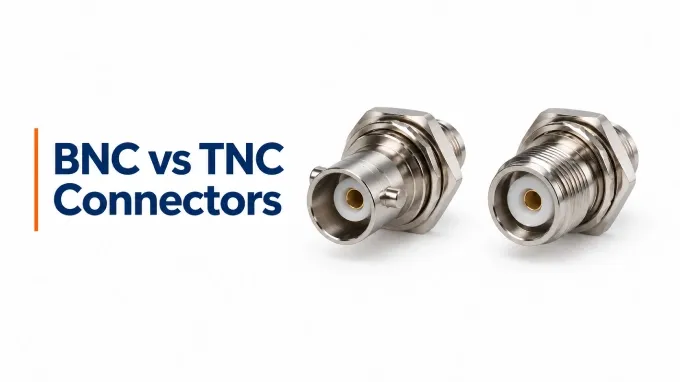
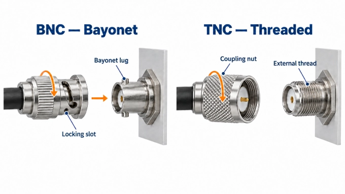
The practical difference between BNC and TNC connectors is the coupling mechanism. A BNC connector uses a fast, quarter-turn bayonet lock, while a TNC connector uses threaded coupling for greater mechanical retention. Both families include 50 Ω and 75 Ω versions.
TNC is generally the stronger starting point where vibration or cable movement is significant, but neither interface is automatically suitable. The required frequency band, system impedance, installed configuration, and documented performance still determine the final choice.
Criterion | BNC | TNC |
Coupling mechanism | Quarter-turn bayonet lock | 7/16-28 UNEF threaded coupling. |
Vibration resistance and stability | Bayonet retention | Greater stability |
Impedance | 50 Ω and 75 Ω | 50 Ω and 75 Ω |
Frequency range | Commonly DC - 4 GHz, extended up to 12 GHz | Commonly DC - 11 GHz, extended up to 18 GHz |
Materials and plating | Copper-alloy contacts, gold or nickel plating, and PTFE dielectric | Similar contact alloys, plating, and dielectric |
Contact resistance | center ≤1.5 mΩ; outer ≤1 mΩ | center ≤1.5 mΩ; outer ≤1 mΩ. |
Temperature range and environmental sealing | −65°C to +165°C; IP67 designs available | −65°C to +165°C; IP67 designs available. |
Price | Example unit price: US$3.10 | Example unit price: US$3.30. |
Coupling Mechanism
BNC: uses a bayonet lock: two lugs on the jack engage slots in the plug’s coupling sleeve. After insertion, a short rotation moves the lugs into their locking positions. This provides a quick connection without threading the mating halves together.
TNC: replaces the bayonet mechanism with a 7/16-28 UNEF threaded coupling. Turning the plug’s coupling nut onto the jack draws the mating halves into their seated position. Connection and release require several turns rather than BNC’s approximately quarter-turn action.
Vibration Resistance and Connection Stability
BNC: A BNC connector can remain physically mated while movement changes the condition of its center- or outer-contact interface. Vibration-qualified BNC designs are available.
TNC: Threaded TNC coupling normally limits this movement more effectively, but it is not immune to loosening or contact disturbance.
It is therefore important to distinguish retention—the connector staying attached—from electrical stability throughout vibration. Published specifications for paired 50 Ω BNC and TNC series from the same manufacturer both list MIL-STD-202, Method 204, Condition B vibration testing. This shared test designation does not establish identical electrical behaviour during vibration.
For detailed failure mechanisms, qualification conditions, and test criteria, see our guide to microwave connector vibration resistance.
Impedance and Mating Compatibility
BNC: Available in 50 Ω and 75 Ω versions, using the BNC mating interface. Availability varies by connector configuration.
TNC: Also available in 50 Ω and 75 Ω versions, using the TNC mating interface. The shared impedance options do not make it mechanically interchangeable with BNC.
The two interfaces do not mate directly; changing between them requires an adapter or a cable assembly with different connector types at its ends. Mechanical compatibility and impedance compatibility are separate requirements: a 50 Ω TNC is not an electrically equivalent replacement for a 75 Ω BNC.
Frequency Range and RF Performance
BNC: Conventional designs commonly cover DC to 4 GHz. Selected extended-range 75 Ω broadcast designs reach 12 GHz when paired with compatible cables and terminations.
TNC: Conventional designs commonly cover DC to 11 GHz, while extended-range designs reach 18 GHz. The actual rating depends on the configuration.
These are family maxima, not ratings shared by every part number. A connector’s frequency rating identifies the band over which its manufacturer specifies acceptable performance under stated conditions.
One manufacturer’s paired 50 Ω series illustrate that RF specifications can overlap:
Published specification | BNC | TNC |
Typical return loss, straight cable connectors | ≥20 dB | ≥20 dB |
Insertion-loss limit at 4 GHz, calculated from each published expression | ≤0.20 dB | ≤0.20 dB |
These are series-specific examples, rather than universal BNC or TNC ratings.
Both VSWR and return loss express the magnitude of the same reflection coefficient on different scales. Lower VSWR is better, while higher positive return loss is better. TNC’s coupling alone does not guarantee better matching; insertion loss describes transmitted-power reduction separately. For deeper explanations, see VSWR and return loss and high-frequency RF connectors.
Dimensions and Size
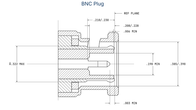
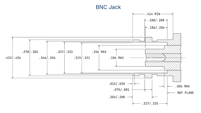
BNC: Body length and coupling diameter vary with connector orientation and cable termination.
TNC: Threaded coupling does not inherently make it larger; comparable plug bodies can have the same dimensions.
BNC Connector Male (Plug) & Female (Jack) Dimensions
TNC Connector Male (Plug) & Female (Jack) Dimensions
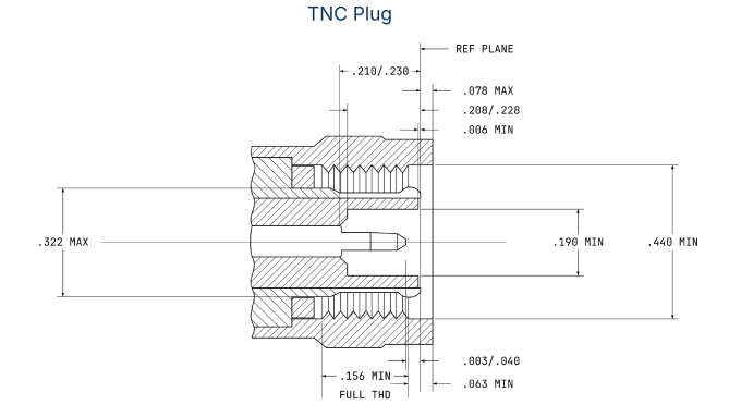
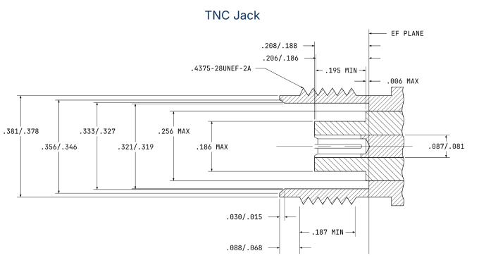
REF indicates a reference dimension. These measurements exclude separate ferrules and boots. Standardized mating-interface dimensions are distinct from the complete connector housing; neither family has one universal overall size.
Materials and Plating
BNC: Representative designs use brass bodies and contacts, gold-plated center contacts, and PTFE dielectric.
TNC: Comparable designs use the same materials. Threaded coupling does not inherently require different contact alloys, plating, or dielectric.
Published 50 Ω constructions illustrate this overlap:
Component | BNC examples | TNC examples |
Body | Nickel-plated brass | Nickel-plated brass |
Center contact | Gold-plated brass | Gold-plated brass |
Outer contact | Brass; nickel, silver, or white-bronze plating | Brass; nickel or white-bronze plating |
Dielectric | PTFE | PTFE |
These examples describe particular constructions; materials and finishes vary by product.
Contact Resistance
BNC: Contact resistance is specified separately for the center contact and outer contact.
TNC: Uses the same distinction; threaded coupling does not establish inherently lower contact resistance.
The referenced paired 50 Ω series publish identical limits:
Contact-resistance limit | BNC | TNC |
Center contact | ≤1.5 mΩ | ≤1.5 mΩ |
Outer contact | ≤1 mΩ | ≤1 mΩ |
These are series-specific specifications, with no universal winner. Contact resistance is a DC property; it is distinct from characteristic impedance and does not, by itself, establish RF insertion loss.
Temperature Range and Environmental Sealing
The referenced 50 Ω series publish identical temperature limits. These specifications are separate from the sealing examples below.
Published specification | BNC | TNC |
Operating temperature, paired series | −65 °C to +165 °C | −65 °C to +165 °C |
BNC: IP67 variants include bulkhead jacks tested in both mated and unmated conditions.
TNC: IP67 variants include cable assemblies with sealed connector interfaces and cable terminations.
Threading provides mechanical retention, not environmental sealing. An ingress-protection rating applies to the documented connector condition or assembly boundaries; protection at a mated interface does not automatically establish protection when unmated or at panel and cable-entry seals.
Applications
BNC: Common in instrument connections that are frequently reconfigured, as well as video signal paths.
TNC: Common in installed antenna and RF connections, with additional uses in instrumentation and industrial equipment.
Application | BNC examples | TNC examples |
Laboratory instrumentation | Oscilloscopes and signal generators | RF test and measurement equipment |
Broadcast and surveillance | Broadcast video and camera connections | Broadband and broadcast equipment |
Antennas and wireless systems | Radio and antenna connections | Antenna feeds and wireless infrastructure |
Industrial equipment | Instrumentation and control connections | Industrial RF and automation systems |
These applications overlap; neither interface belongs exclusively to one industry.
Price
BNC: The selected crimp plug has the lower unit price in this comparison.
TNC: The corresponding plug costs US$0.20 more, a difference specific to these two products.
Prices compare products from the same manufacturer and seller. They illustrate one pair rather than a market-wide premium; construction, performance grade, supplier, and quantity affect pricing.
How to Choose Between BNC and TNC Connectors
Start with the equipment interface. Match the RF connector family, system impedance, and standard or reverse-polarity configuration. Verify the exact mating counterpart, including its center-contact arrangement.
Establish the required operating band. Compare documentation for the actual connector, orientation, termination, cable, and mating counterpart. Check matching and insertion-loss limits across the complete operating band. Make the final selection using documented performance for the complete installed configuration.
Prioritize connection behaviour. If rapid reconnection is the dominant requirement, BNC may be suitable when the specific configuration meets the electrical and mechanical requirements. If stronger retention under movement is the dominant requirement, TNC may be suitable. Fully engage the BNC lock; start TNC coupling threads by hand and tighten according to the specific connector’s instructions.
Confirm environmental and physical fit. Check sealing conditions, operating temperature, cable compatibility, and coupling access. When specifying custom RF cable assemblies, cable flexibility, routing, strain relief, termination, and mounting support should be evaluated together with the coupling type.
Compare equivalent options. Evaluate price after the technical requirements are satisfied. Compare the same cable compatibility, mounting style, environmental protection, and performance grade at the same purchase quantity.
FAQ
Discussion (0)
Be the first to comment.