What Is the Difference Between SMA and SMB Connectors?

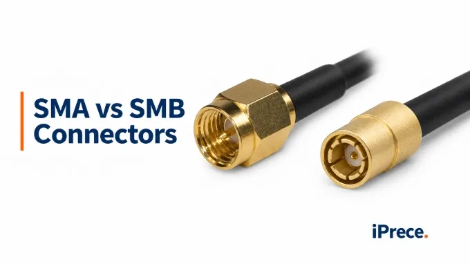
The primary difference is the coupling mechanism: an SMA connector uses a threaded interface, while an SMB connector uses a snap-on interface. SMA generally supports a wider microwave frequency range and provides controlled mechanical retention, but it requires sufficient access and correct tightening. SMB enables faster mating in a smaller installed space, although its retention must be evaluated against cable loading and vibration. The correct choice therefore depends on the required RF performance, assembly layout, servicing method, and mechanical environment.
How Do SMA and SMB Compare in Frequency and RF Performance?
SMA has the higher general frequency capability, but maximum frequency alone does not determine whether either interface will meet a system requirement. Engineers must compare the relevant connector configurations across the actual operating band and account for the transitions surrounding the mating interface.
What Do Frequency Ratings and Nominal Impedance Actually Establish?
The standard iPrece SMA range is specified from DC to 18 GHz, with extended-range configurations reaching 34 GHz. Standard iPrece SMB configurations cover DC to 4 GHz, while extended-range versions reach 10 GHz.
Both iPrece families use a 50 Ω nominal impedance for this comparison. Nominal impedance identifies the system standard, but it does not show how closely the assembled interconnect remains at 50 Ω through every transition. SMB interfaces are also used in some 75 Ω systems, so engineers must verify impedance rather than assuming that mechanically similar SMB components are electrically interchangeable.
For connectors installed in custom RF cable assemblies, the connector rating establishes only one limit. The cable, connector-to-cable transition, termination workmanship, orientation, and assembly length can all constrain the finished assembly’s usable bandwidth and RF performance.
Does SMA Necessarily Provide Better VSWR, Return Loss, and Insertion Loss?
SMA does not automatically provide better RF performance in every shared operating band. Its geometry supports substantially higher frequencies, and well-designed SMA configurations often provide tighter matching, but a family-level comparison cannot establish the performance of two specific interconnects.
A valid comparison should use:
The same frequency band and 50 Ω reference impedance
Comparable straight, right-angle, cable-mount, or PCB-mount configurations
Reference planes that include equivalent portions of each interconnect
Frequency-dependent S11 or S22 and S21 data
Clearly identified maximum or typical limits
Measurement uncertainty or suitable guard bands near the acceptance limit
VSWR and return loss express the magnitude of the same reflection. For an input reflection coefficient :
Return loss is normally reported as a positive value, while S11 in logarithmic magnitude is usually negative. A 20 dB return loss therefore corresponds to S11 of −20 dB. Better matching produces higher positive return loss, more-negative S11, and a VSWR closer to 1:1.
As an illustrative design requirement, suppose the interconnect must maintain at least 20 dB return loss across its operating band:
The equivalent requirement is therefore a maximum VSWR of approximately 1.22:1.
Insertion loss must be assessed separately through S21. Two interconnects can have similar return loss while differing in conductor loss, dielectric loss, transition loss, or radiation leakage. Straight and right-angle bodies, cable terminations, and PCB launches can also produce different results within the same connector family. The VSWR expressions published on the iPrece parent pages apply to different cable and orientation combinations, so comparing those numbers directly would not isolate the connector-interface difference.
For phase-sensitive systems, acceptable return loss and insertion loss still do not establish transmission-phase stability. That requires phase data under the relevant temperature, flexure, vibration, and remating conditions.
How Do Threaded and Snap-On Coupling Affect Mating and Mechanical Reliability?
The coupling mechanism changes how the connector is installed, retained, and serviced. SMA requires controlled thread engagement and tightening, while SMB permits faster tool-free mating. Neither mechanism alone establishes service life, RF repeatability, or suitability for vibration.
What Changes During Mating and Repeated Servicing?
SMA mating takes longer but allows the installed connection to be tightened to a defined condition. SMB supports faster connection and removal, provided the interfaces are aligned and fully engaged.
SMA: Bring the interfaces together axially, start the threads without cross-threading, and rotate the coupling nut rather than the connector body or cable. Apply the specified SMA connector torque while restraining the body at its wrench flats when required.
SMB: Align the interfaces and push them together axially until the snap-on mechanism fully engages. During disconnection, grip the intended connector body and pull along the mating axis rather than loading the cable or termination.
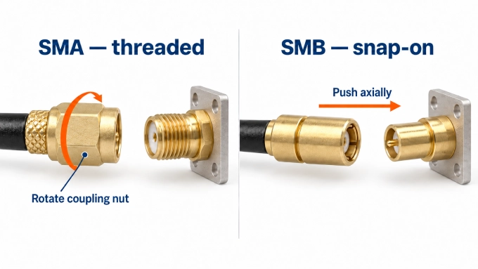
SMA and SMB interfaces do not mate directly. Connecting them requires an appropriate adapter, which becomes an additional electrical and mechanical element in the signal path.
Faster mating does not mean that SMB has a longer qualified life. The iPrece SMA and SMB pages both specify a minimum of 500 mating cycles. That figure describes performance under the applicable test conditions; it does not predict service life under contamination, side loading, poor alignment, incorrect SMA tightening, or cable-assisted disconnection. The detailed SMA connector mating cycles discussion therefore belongs to lifecycle planning rather than serving as a simple family ranking.
Mechanical cycle qualification also does not guarantee identical RF response after every reconnection. A connector may still mate securely while contact wear, transferred debris, or dimensional damage changes the interface condition. Where remating repeatability affects measurement uncertainty or system calibration, it must be evaluated electrically across repeated controlled connections.
What Determines Stability Under Vibration and Cable Loading?
Threaded SMA coupling generally provides stronger resistance to axial separation when correctly engaged and tightened. SMB relies on its snap-on retention mechanism, so incomplete engagement or sustained axial cable force can be more consequential. However, SMA can loosen or suffer termination damage, while properly selected SMB configurations can pass defined vibration tests.
The main failure paths are:
Separation or loosening: The coupling backs off, releases, or was not fully engaged before operation.
Contact micromotion: Small relative movements occur at the center or outer contacts even though the connector remains visibly mated.
Mount or termination damage: Cable mass and movement load the crimp, solder joint, panel mount, or PCB attachment rather than separating the interface.
Cable routing therefore forms part of the mechanical design. Strain relief should prevent tensile, bending, and torsional loads from reaching the mating interface. Board-mounted connectors also need adequate mechanical support so that cable movement does not transfer bending moment into the launch or PCB solder joints.
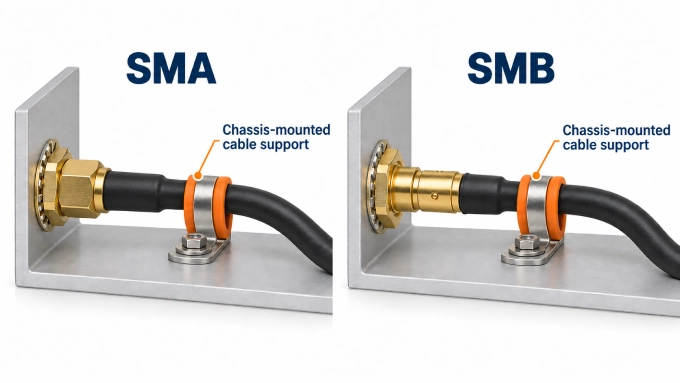
Published connector vibration resistance should be assessed against the installed configuration rather than inferred from “threaded” or “snap-on.” Useful qualification evidence must represent the required vibration profile, axes, duration, mounting method, cable type, routing, and supported cable mass. The acceptance criteria must also address the behavior that matters to the system, such as unintended unmating, intermittent contact, or unacceptable change in RF performance during or after exposure.
Does SMB Save Space in the Installed Assembly?
SMB often provides a packaging advantage, but the connector body alone does not determine usable space. The comparison must include the mated pair, cable transition, operating clearance, and mechanical support. A compact connector that cannot be reached or disconnected after installation may produce a poor service layout.
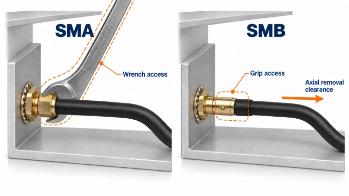
PCB attachment must also support the expected cable forces without transferring excessive load into the solder joints or board launch. Right-angle cable exits can reduce enclosure depth, while straight exits may simplify routing when axial clearance is available.
Which Engineering Requirements Favor SMA or SMB?
SMA is generally favored when the operating band, documented microwave performance, or controlled retention dominates the design. SMB becomes attractive when both interfaces meet the electrical requirements and assembly density or rapid service access has greater value.
Microwave LO or RF Connections Between Modules
SMA is usually the stronger candidate for wideband or higher-frequency signal paths because more SMA configurations provide documented microwave performance. An extended-range SMB may still be suitable when its guaranteed data cover the complete operating band, transitions, and required design margin.
Internal IF or Reference Connections Requiring Service Access
SMB can reduce servicing time when technicians must regularly connect or replace internal cables. SMA may remain preferable when cable loading, mechanical retention, or consistent reconnection has greater importance than mating speed.
Phase-Sensitive Measurement Paths
SMA is generally the better starting point, but the decision must use measured evidence rather than the connector name. Evaluate phase stability and measurement uncertainty across controlled remating cycles. A characterized SMB assembly may be acceptable at lower frequencies when its repeatability meets the system limit.
Instrument or Telemetry Harnesses Exposed to Vibration
SMA or a vibration-qualified SMB configuration may be suitable. Acceptance depends on the installed cable support, mounting method, retention, vibration profile, and electrical results during or after testing. Coupling style alone does not establish reliability in the final assembly.
Dense Multichannel Assemblies
SMB often supports higher connection density when its smaller installed envelope and axial mating method fit the assembly process. That advantage can disappear if adjacent components prevent gripping the connector, the enclosure lacks removal clearance, or the cables cannot maintain their required bend radius.
The operating band should serve as the first exclusion criterion. When both families meet it, compare measured assembly performance, installed clearance, service procedure, cable loading, and environmental qualification. This avoids selecting SMA solely for its higher family-level frequency capability or SMB solely because it appears smaller and faster to connect.
FAQ
Discussion (0)
Be the first to comment.